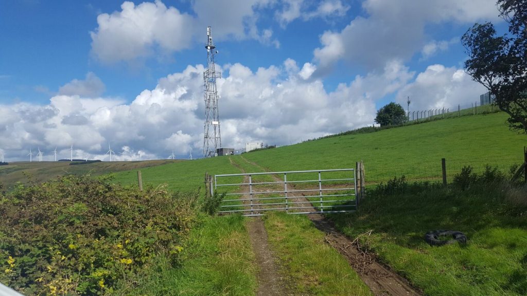
Internal Database Makes KAEG Faster, Smarter

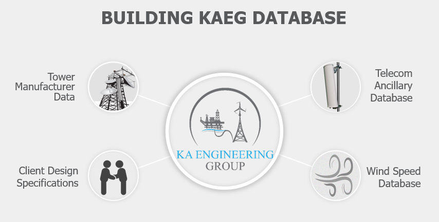
KA Engineering Group has just celebrated our 3-year anniversary. Since the business established in 2018, we have treated data as a valuable asset and started to build an internal specialised database including wind speed dataset, ancillary parameters, tower manufacture details, client design specifications and design guidelines for different structures, etc.

Each passing day means that not only do our design capabilities and project experience improve but our internal database becomes bigger, better and smarter. Our in-house database allows our engineering work to be streamlined and standardised so that we can provide our clients with economical and fast turnaround design solutions.

With the help of our database, it is possible that performing a full tower climbdown survey can be eliminated, saving time and cost for clients. If climbdown survey is required, we can also offer guidance and provide KA survey template that lists all design data required for structural analysis to avoid the lack of key information and a costly site revisit. We also have the ability to support the entire construction/modification process of telecom towers and rooftop structures, from survey through to structural design and completion.

KAEG are always passionate in pursuing engineering excellence, best design practice and new technology to provide our customers with cost-effective, reliable and fast turnaround design solutions. Contact our expert team at: info@ka-engroup.com to learn more and discuss how we can best serve your needs.

Impact of Feeder Arrangement

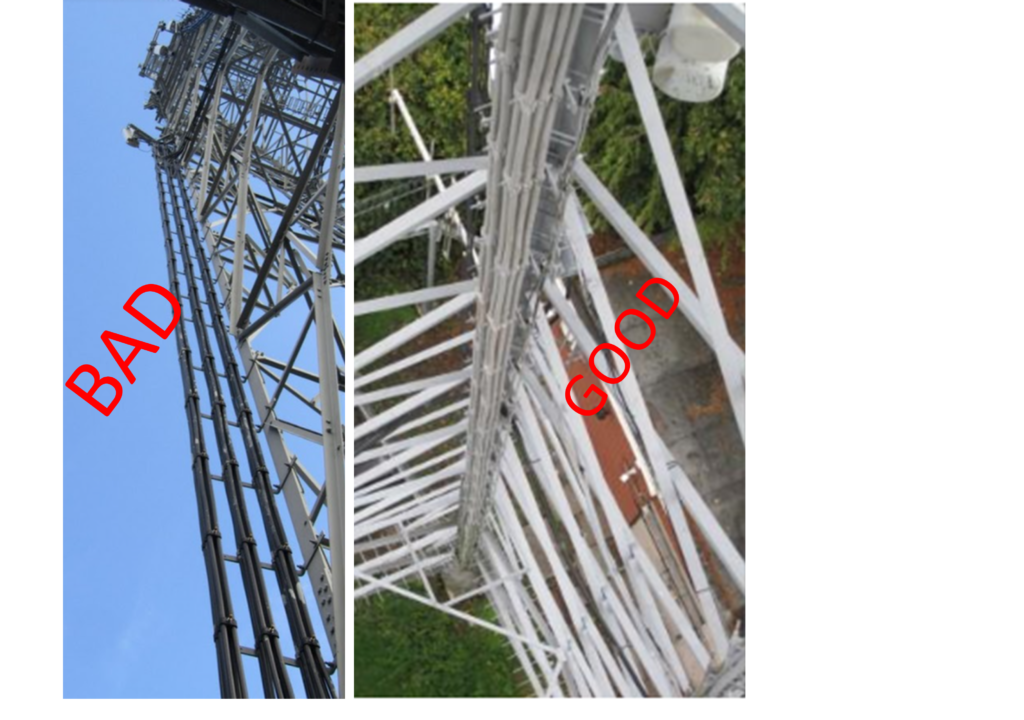
Feeder cables can FAIL a lattice tower, through exceeding the structural utilisation capacity, if not arranged thoughtfully. Carefully planned feeder arrangement in a simple system can reduce the utilisation of the lattice tower legs by 15% and reduce the tower brace utilisation by nearly 40%!

Without adequate forethought, a telecommunication system with 16 feeder cables on a tower may be arranged in stacks of 1 or 2. This leads to wind load across eight, or even 16 feeder surface areas.

We investigated the effect of feeder arrangements on tower utilisation. We placed four antennas at the top of an existing 30m square lattice tower, fed by 16 typical sized feeders in a variety of different arrangements. To replicate a common tower arrangement, the structure also included a ladder mounted on one of the tower faces.

What We Found

Our analyses showed the maximum tower utilisation with the feeders stacked in a single row of 16, mounted on one leg, adjacent to the ladder location. Minimum utilisation was from feeders stacked in rows of four, mounted on a leg that is not directly supporting the ladder.

The difference in structural utilisation between these two scenarios was 15% for the tower legs, and 38% for the tower braces!

A surprising find was the structural utilisation from the feeders separated into groups of four, stacked in rows of two, mounted on each leg. The leg and brace utilisation were greater than those in the minimum scenario by 5% and 6% respectively.

Take Away Message

Feeders must be arranged with tower loading in mind. With less loading from feeders, more ancillaries can be placed on the tower, resulting in a more useful AND more financially profitable structure.

Check your existing towers. Check your proposed towers. Think about how the feeders are, or are proposed to be, arranged:

  • Are the feeders helping to distribute the loads more evenly throughout the tower?
  • Are the feeders stacked in the most efficient manner to reduce wind load on the structure?

KAEG continues to leverage our expertise to maximise the structural potential of your asset. Contact our expert team at: info@ka-engroup.com to learn more and discuss how we can best serve your needs.

Tower Strengthening Project

At KA Engineering Group, we analyse a wide range of structures from monopoles to lattice towers and everything in-between. We recently completed the analysis of  an existing 48m tower for the proposed addition of a 2-meter microwave dish.

Using a combination of the information from previous site surveys, as-built construction drawings, and photographs, we produced a detailed 3D finite element model. We then applied wind, weight and ice loads based on British Standards and European Codes.

The tower had previously been strengthened through the addition of circular hollow sections (CHS) braces at various elevations. We found that these sections were themselves over-utilised and were adversely affecting the load distribution within the tower. As a result of this finding, the client was informed to remove the existing strengthening solution and to complete a more targeted strengthening scheme which brought the tower utilisation down to 80% providing more capacity for the future.

In addition to the strengthening solution analysis, we provided a general arrangement and fabrication drawing to clearly illustrate the sections that are to be replaced on the structure. KA Engineering Group not only completes structural due diligence for all telecommunication support structures, we also take further responsible steps to consider, advise, and optimise each site, ensuring cost effective design, installation, and maintenance for build contractors and efficient utilisation for operators.

Contact our expert team at: info@ka-engroup.com to learn more and discuss how we can best serve your needs.

Anchors Embedded in Masonry

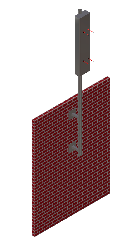
In wall mounted pole structures, the function of anchor bolts is to transfer design forces such as uplift due to wind or vertical gravitational loads to the masonry. KAEG employs advanced engineering best practices to more consistently design and analyse anchors in order to ensure the installation properly embody its requirements.

The method of calculating the pull-out load is based on the shape of the failure surface, a truncated cone, observed during base material failure (Destructive loading). The proof test load is determined through structural analysis of two scenarios; wind perpendicular to wall and wind parallel to wall, taking ancillary orientation into account.

Anchors are tested (Non-destructive loading) with a pass result prior to installation to the calculated proof test load to confirms the holding power of anchors for the purpose of providing assurance of correct installation.

In the event that the calculated pull out load values is high, either load bearing internal back-plates or additional back-plated brackets are installed to strengthen the wall mounted connection, which negates the need to proof test the anchors.

Unlike concrete, masonry walls are not uniform base material and the location of the anchors in the wall affect the performance. Therefore, anchor designs require careful considerations in order to ensure that the applied loads are sufficiently distributed and the masonry is robust.

KAEG are at the forefront of providing valued engineering to achieve cost- and installation effective design solutions in the telecommunication industry to network providers. Contact our expert team at: info@ka-engroup.com to learn more and discuss how we can best serve your needs.

Freestanding Ballast Frames

The design of free-standing rooftop structure in accordance with design codes to serviceability criterion is a fundamental first principle design that can be completed by the old-school pen and calculator method, but the solution is often over- or under-designed. The designed solution must be adequate to ensure that the structure is stable against overturning moment (OTM) and sliding forces caused by wind action in addition to eccentric weights, accounting for the ancillaries, steelwork, and ballast frame.

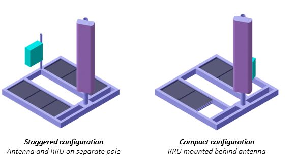
Overturning moments are primarily due to wind forces in addition to eccentric vertical loads about the global centroid of structure. This de-stabilising load must be balanced and counteracted to achieve structural stability and safe operations.  More often, simplified method is adopted that only considers the destabilizing and stabilizing forces on one side of the structure which is not always the optimal design. Configuration optimisation is essential to achieve cost and installation effective solution such as reduced ballast frame size and induced pressure on the roof. This includes:

  1. Positioning the antennas and associated RRUs in a staggered configuration to reduce unfavourable eccentricity.
  2. Compact configuration which involve shielding the RRUs behind the antennas to reduce the wind destabilsing force.

KAEG are at the forefront of providing valued engineering to achieve cost- and installation effective design solutions in the telecommunication industry to network providers. Contact our expert team at: info@ka-engroup.com to learn more and discuss how we can best serve your needs.

Installation of Multiple Antenna Per Sector

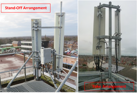
With increasing demand and fast changing technology, there is often a need to install two antennas in each sector to cover a large range of technology. Sometimes, there is enough space to install the antennas on separate primary poles, but often space is limited. For these cases, it is necessary to accommodate both antennas on a single primary pole with desired spacing to avoid clipping. There are two configurations available:

  1. Standoff system – One antenna on an offset pole using standoff bracket, and the other antenna on primary pole itself,
  2. Yoke system – Both antennae on offset poles using yoke bracket.

A standoff arrangement is often utilised when one antenna is an existing antenna and it belongs to another operator and hence it cannot be moved. However, it is an unfavourable arrangement.  Due to the antenna overhang on one side, the standoff system results in eccentric loading on the primary pole which requires bigger section to support. This also transmits higher bending loads on the primary structure.

A yoke arrangement is preferable as carries two antennae on either side of the primary pole. It can provide the desired spacing between the two antennas to avoid clipping, with less overhang. It also balances the wind load and weight from either side of the bracket and results in lower bending and torsional moments on the yoke bracket and primary pole.

This ultimately results in saving material by reducing the need to have bigger and stronger steel sections.

KAEG are at the forefront of providing cost-effective design solutions to over-stressed telecommunication structures to ensure continuous safe operations. Contact our expert team at: info@ka-engroup.com to learn more and discuss how we can best serve your needs.

Support Design for Cantilever Systems

Cantilever poles are used throughout the telecommunication industry to support ancillaries such as antennas and dishes. Frequently, the introduction of a proposed ancillary can exceed the capacity of the existing cantilever system, requiring new design requirements, new installations, and consequently, more money. There is a common misconception surrounding how to increase the capacity of a cantilever system.

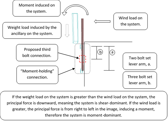
There are two ways in which cantilever systems are significantly loaded, they can either be shear-dominant or moment-dominant (shown below):

If the system is shear-dominant from the forces presented (i.e. the weight load is greater than the wind load), and the connections consist of two sets of two U-bolts, the bolts will be loaded in shear. For this condition, the greater number of bolts, the more secure the connection. However, in a moment-dominant system, the wind force has a greater effect on the system than the weight load, inducing a moment on the connections. In a moment-dominant system, the distance between the two sets of bolts (or “lever arm”) is the main influence.

If the moment induced on the system is anticipated to exceed the capacity of the existing bolt arrangement, placing a third bolt connection into the system between the existing bolt sets actually reduces the capacity of a moment-holding connection. This is because the lever arm length is reduced in the connection: from the distance between the upper and lower bolt sets, to the upper and central bolt sets.

To conclude, for a shear-dominant cantilever system, a third set of bolts is an appropriate solution. However, for a moment-dominant cantilever system, a better solution is to increase the distance between the existing bolt connections, increasing the capacity of the cantilever system.

KAEG are at the forefront of  providing cost-effective strengthening solutions to over-stressed telecommunication structures to ensure continuous safe operations.

Contact our expert team at: info@ka-engroup.com to learn more and discuss how we can best serve your needs.

Assessing Wall and Connections for Reusable Wall Mounted Ancillary Steelwork

In our previous blog (click here to read), we discussed the structural and health and safety concerns arising from the increasing number of wall mounted ancillary failures recorded in recent times. These failures are often due to the growing need to utilise existing wall mounted steelworks to support bigger and heavier antennas without appropriate structural assessment.

In this post, we offer advice on how to structurally assess reusable wall mounted steelwork for new installations. The advice is valid for both major types of mounted steelwork connections:

  • Chemical resin connection – where are anchors buried into the fabric of the wall.
  • Mechanical connection – where anchors are put through the wall and fixed to backing-plates on the inner wall fabric.

An appropriate structural engineering methodology to assess the suitability of existing wall mounted systems must include:

  1. Complete non-intrusive structural inspection of existing mounted steelwork to determine;
    • Type and condition of anchor connections to wall;
    • Nature and type of wall (block/brick work and mortar joints) including natural degradation leading to loss of integrity of wall capacity and connections;
    • Presence of though-wall or surface cracks;
    • Presence of internal face back-plates;
    • Installation near wall edges and on mortar joints;
    • Inadequate and porous resin around anchors and loosed bolts;
    • Existing steelwork dimensions;
  2. Structural testing of existing steelwork anchors to obtain wall pull-out proof loads in accordance with guidelines from the Construction Fixings Association (CFA);
  3. Numerical structural analysis of existing steelwork for the proposed new antennas/dishes incorporating findings from part (1) to;
    • Establish that the utilisation of existing steel work for new loads is within allowable capacity
    • Establish that the new anchor pull-out loads to compare are within pull-out test capacity obtained via intrusive inspection in part (2).

KA Engineering Group not only completes structural due diligence for all telecommunication, subsea risers, onshore and offshore renewable wind turbines support structure, we also take further responsible steps to consider, advise, and optimise each site/field, ensuring cost effective design, installation, and maintenance for build contractors and efficient utilisation for operators.

Contact our expert team at: info@ka-engroup.com to learn more and discuss how we can best serve your needs.

Inspecting Wall and Connections for Reusable Wall Mounted Ancillary Steelwork

Wall mounted steelworks are an acceptable and standard option of supporting telecommunications ancillaries, especially within urban areas where strict planning restrictions limit the use of lattice towers and monopoles. The ancillaries are typically mounted on steel support poles that are offset from the wall using steel brackets and/or stub arm to the wall.

The steelwork is connected to the wall via:

  • Chemical resin connection – where anchors buried into the fabric of the wall.
  • Mechanical connection – where anchors are put through the wall and fixed to backing-plates on the inner wall fabric.

The anchor design may use 2 or 4 anchor stud configurations per connection as per structural requirement.

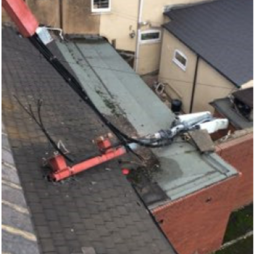
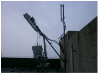
There is a growing need to utilise existing wall mounted steelworks to support bigger and heavier antennas due to continuous technological improvements and ancillary upgrade to meet increasing demands. However, re-using existing wall mounted steelwork to support these bigger and heavier antennas is not without structural and health and safety concerns as evidenced by the increasing number of failures recorded in recent times.

These failures are partly due to inadequate structural assessment to account for increased loading from the proposed antennas/dishes. The proposed ancillaries may impose loads that are greater the design capacity of existing steelworks and associated connections to the wall causing failure.

The challenge is to define suitable methodology to structurally assess existing wall mounted systems to ensure safe reusability. We will discuss methods and solutions to this issue in more detail in the next blog.

However, the salient points for consideration when assessing these installations include:

  • Inadequate original design (including reusability assessment) and proof testing of anchors to Construction Fixings Association (CFA);
  • Insufficient spacing between top and bottom connections to wall;
  • Mortar joints between bricks and/or block work;
  • Cracked bricks and/or block work;
  • Installation near wall edges and on mortar joints;
  • Inadequate and porous resin around anchors and loosed bolts;
  • Age and nature of building- natural degradation leading to loss of integrity of wall capacity and connections;
  • Correct fabrication and installation of original steelwork and connection to wall.

KA Engineering Group not only completes structural due diligence for all telecommunication, subsea risers, onshore and offshore renewable wind turbines support structure, we also take further responsible steps to consider, advise, and optimise each site/field, ensuring cost effective design, installation, and maintenance for build contractors and efficient utilisation for operators.

Contact our expert team at: info@ka-engroup.com to learn more and discuss how we can best serve your needs.

Overview of Telecom Support Structures

The ever-increasing demand for mobile telecommunication, radio, radar, and television communications means that more and more individuals (technical and non-technical) are encountering the telecoms industry. There is therefore the need for a simplified overview/general specification to provide internal and external stakeholders/investors, users, non-technical and technical professionals with the basic knowledge and understanding of telecoms structural engineering.

This post presents the various key classes of telecommunication support structures that are instrumental in the continued success of data transmission.
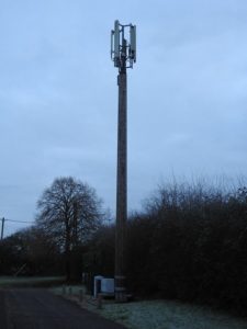
Self-Supporting Monopole Towers

Monopole towers comprise of constant tapered steel tubes or segmented tubular steel section that are welded or bolted to each other to form a pole decreasing in diameter from the bottom to the top. Sections are usually made from hollow, heavy duty, thick steel tubes, flanged steel tubes or low-alloy, high-strength steel, finished to meet required local aesthetics.
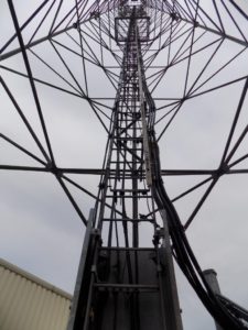
 

Self-Supporting Lattice Towers

Self-supporting lattice also known as free-standing lattice tower structures consist of truss sections joined to form tapered or straight panel sections. The tapered panel sections have face width that vary according to height and load capacity. Lattice towers can have triangular (tripod) or square (quadpod) footprint. The truss members are commonly hollow tube, equal angle, or solid round bar. Although other section types such as folded (<90deg) steel angle are possible.
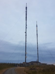
 

Guyed or Stayed Lattice or Monopole Towers

These are lattice or monopole towers similar in design to the self-supporting tower class except that they are further stabilised by tethered wire or rope systems. Guy wires are made from pre-stretched steel only and care must be taken to ensure that they are not be over tightened during installation and in-service to avoid misalignment, cable rupture and permanent wrapping of the tower structural members. Additionally, structural design of the guy anchor shall consider the nature and bearing capacity of the soil.


Roof and Wall Elevated Mounts
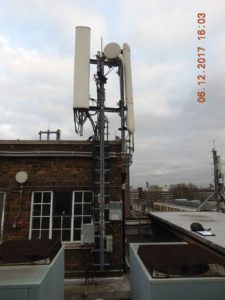
Roof and wall elevated mounts can be an inexpensive way of elevating signals above roof interference or other obstructions by mounting the equipment atop an already high and stable structure (e.g. rooftop of a high-rise building). Roof mounts can be penetrating (impacting) or non-penetrating (non-impacting) installations and can also be self-supporting or guyed. In all cases, structural checks and certification by competent engineering team must be made to establish the capability of the roof to withstand the additional imposed loads due to the proposed ancillaries and steelwork installations.


KA Engineering Group does not only complete structural due diligence for all these telecommunication support structure classes, we also take further responsible steps to consider, advise, and optimise each site, ensuring cost effective installation and maintenance for build contractors and efficient utilisation for operators.

Contact our expert team at: info@ka-engroup.com to learn more and discuss how we can best serve your needs