Avoiding Structural Failures in Telecom Installations: Overloading of Existing Structures
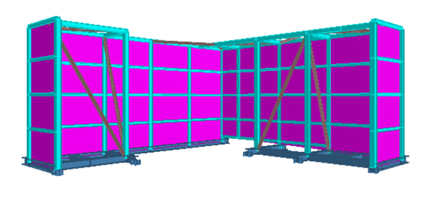
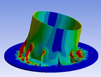
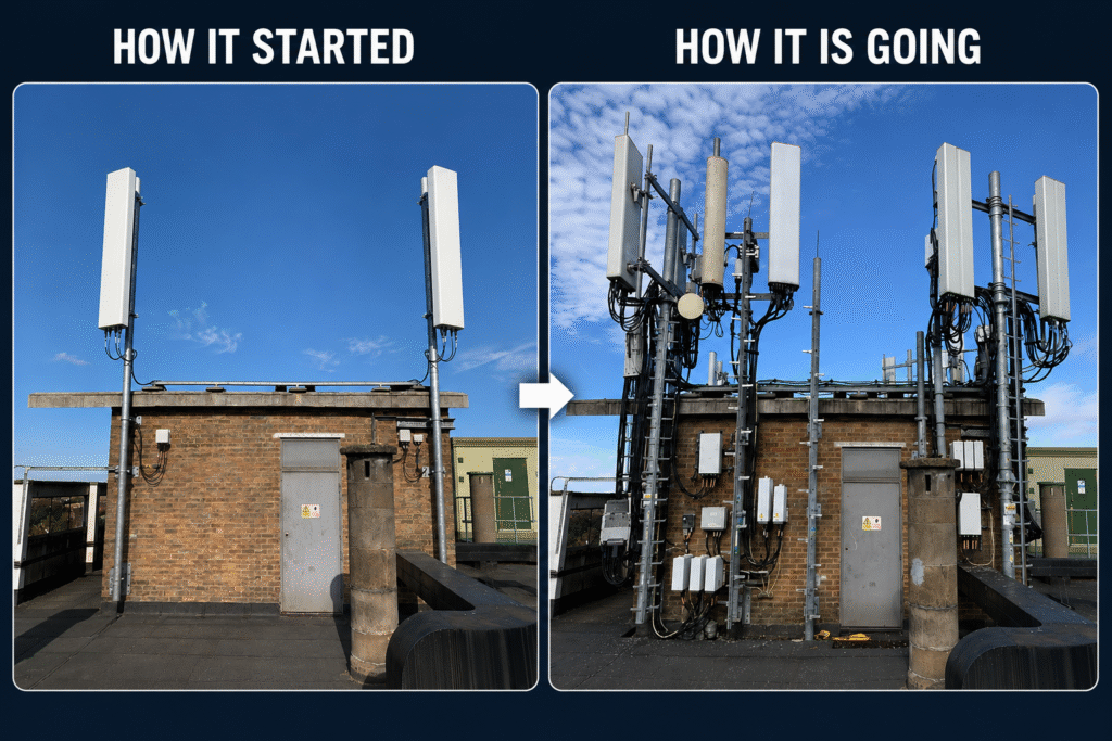
Telecom installations are often treated as minor additions to existing structures, but they can introduce significant loads that were not considered in the original design. Without proper assessment, this can lead to overloading and potential structural failure. One of the most common issues is the assumption that rooftops and supporting elements have sufficient capacity to […]