Bamboo to Replace Telecom Steel?

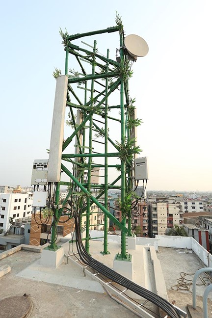
Assuming that we can keep the Pandas at bay, should we be looking at replacing steel with bamboo? Can bamboo telecommunication towers be sustainable and economical? Telecom towers are usually fabricated using steel because steel has very good strength. However, due to its tightly packed fibres, bamboo has superior tensile strength over steel. Producing steel also has a lot of drawbacks like high costs, atmospheric pollution, and environmental degradation. Bamboo, on the other hand, can be produced at very low costs and has various environmental benefits.

So far so good! Unfortunately, tensile strength alone is not sufficient. Bamboo is prone to insect attacks and will degrade until sustained exposure to water which is an issue for any towers not installed in the Sahara!

Perhaps the future of bamboo will depend on its use as a composite material or more resistant strains will be cultivated to remove some of the limitations. Either way, we are excited to see what the future holds.

At KA Engineering Group, we like to think of ourselves as a solution independent structural consultancy. We leverage our extensive engineering experience to accurately design the most suitable telecom structure for your needs. We take responsible steps to consider, advise, and optimise each site, ensuring cost-effective design, installation, and maintenance for build contractors and efficient utilisation for operators. Contact our expert team at: info@ka-engroup.com to learn more and discuss how we can best serve your needs.

Don’t Forget Primary Structure Check for Rooftop Stub Towers

Rooftop stub towers, a solution that has gained popularity for its ability to overcome space constraints and improve connectivity in urban environments. When performing structural analysis on stub towers, it’s easy to focus solely on the tower structure, headframe and secondary steelworks. However, it’s crucial not to overlook the primary structure of the building itself.

The primary structure of a building supports the weight of the entire structure, including the added load of a rooftop stub tower. Conducting a load-bearing capacity assessment is crucial to ensure that the building’s structure can safely accommodate the additional weight and forces imposed by the tower and its equipment. This assessment involves evaluating the roof slab, columns, beams, and other structural elements to determine their ability to bear the load without compromising structural integrity. A thorough structural analysis can also help to determine how the additional weight and forces from the rooftop stub tower are distributed within the primary structure. By assessing load distribution, engineers can identify areas that may require reinforcement or modifications to maintain the stability of the primary structure under varying conditions.

Also, adhering to building codes and regulations is of utmost importance when designing rooftop stub towers. Building codes often outline specific requirements for structural integrity, load capacities, and safety factors. KA Engineering Group possess extensive knowledge and experience during the completion of hundreds of stub tower projects to assess the stub tower and building’s structural capacity.

Contact our expert team at: info@ka-engroup.com to learn more and discuss how we can best serve your needs.

EMA Strengthening Solutions

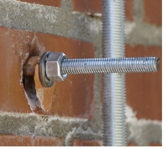
EMA Poles are common telecom structures in city centres. EMA poles are usually held by standoffs attached to a plate and connected to a wall through anchor bolts. The forces generated causes the anchors to want to pull out from the wall. Historically, these anchors are held by chemical resins injected into the wall. Click here for description of chemical resin anchors. Usually, where the pull out load is excessive, the resin anchors become unsuitable to resist pull out and strengthening solutions needs to be adopted where the EMA is existing. There are two possible strengthening solutions

Back plating: This involves using a bolt that passes through the wall to the other end held by a back plate. In this case, pull out of the bolt is resisted by the rigid connection of the plates and nuts at the back. For the bolts to pull-out, the entire wall will have to cave in. Hence, the proposal of a back-end plate negates the need to pull test the anchors.

Over plating: This involves increasing the number of bolts and spacing of the existing anchors. A small Equal angle (EA) steel section is placed over the existing front plate and new bolt holes are drilled at the top and bottom of the EA for new bolts to pass through the wall. This increases the number of bolts and hence reduces the pull-out force as the forces are shared by 6No. bolts as opposed to 4Nos as shown in the fig 2b below.

Lattice Tower Braces

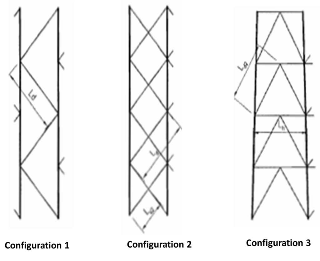
Lattice towers can be braced in various configurations (see image) but have you ever wondered why a particular configuration is selected?

Braces are needed to keep a structure stable and prevent it from swaying or drifting since most towers act as a cantilever system. They transfer lateral loads from the tower to the ground and they also prevent the tower legs from buckling. There are various types of brace configurations but can be broadly simplified to 3 groups.

Configuration 1 is called a Single brace and they are good for resisting light loads for instance near the top of a tower.

Configuration 2 is called a Cross Brace and is capable of withstanding both tensile loads and drifts.

Configuration 3 is called a Chevron/K- Bracing and it is used for controlling deflection and resisting lateral loads.

Other brace configurations are made from a combination of these basic configurations.

At KA we ensure that the right brace configuration is selected to new tower design or applied for strengthening scheme to increase capacity to withstand lateral loads. We also take responsible steps to consider, advise, and optimise each site, ensuring cost-effective design, installation, and maintenance for build contractors and efficient operator utilisation. Contact our expert team at: info@ka-engroup.com to learn more and discuss how we can best serve your needs.

Diversifying Your Skillset

As a structural engineer, it is easy to become so focused on design and analysis that you neglect other valuable skills that can help you excel in your field. While knowledge of codes, standards, and structural theory is essential, it is equally important for engineers to have a diverse range of skills and well-rounded knowledge that can help them stand out in the workplace.

One such skill that can be extremely useful for a structural engineer is the ability to code. This is because quite often, we come across repetitive tasks that require some form of automation through coding. By having the ability to write code, engineers can streamline their workflow, reduce errors, and increase efficiency, allowing them to focus on more complex and creative aspects of their work. Coding also opens up opportunities to work on cutting-edge projects and to develop custom solutions to complex engineering problems. It broadens your perspective, and this can be particularly valuable in the field of structural engineering where new materials, construction methods, and design techniques are constantly emerging.

An example is having some knowledge of Python or VBA that allows you to automate a process and create useful tools that help in your structural calculations.

It is not just structural engineers who can benefit from diversifying their skills, we at KAEG are encouraging all working professionals, regardless of their discipline, to never be so straight-narrowed in their profession and should instead learn complementary skills and diversify. In today’s fast-paced, rapidly changing world, it is more important than ever to be versatile and flexible. Contact our expert team at: info@ka-engroup.com to learn how we can bring our diverse skills to best serve your needs.

Deflection in Telecom Structure Analysis

Deflection in telecommunication structures refers to the deformation or displacement of a structure from its original position under load. Deflection is a serviceability limit, that is, it does not automatically constitute structural failure, thus there are often differing requirements on the acceptable levels of deflection. There are typically two categories of deflection limits considered in telecoms analyses: General structural deflection limit and Operator’s deflection limit.

The operator’s deflection limit is specified by the site operator in the telecoms industry. They specify levels above which the structure becomes unfit for use based on ancillary equipment operational guidelines and specifications.

The general structural deflection limit is specified by design codes e.g., Eurocode & BS code an offers guidance on the level of deflection that will not cause discomfort/alarm to the site users.

The operator’s deflection limit can be a little generous. We often find that a structure can be within it operator’s limit but has exceeded its general deflection limit, therefore a decision must be made. Designing a structure that is below the general structure deflection limit may incur additional costs which the site operator may be opposed to. It is responsibility of the engineer to ensure that all stakeholders participate in the decision making and to balance the interest of all parties.

At KA Engineering Group, we leverage our extensive engineering experience to accurately design any form of telecoms structure ranging from complex GDC to basic DD analysis. We take responsible steps to consider, advise, and optimise each site, ensuring cost-effective design, installation, and maintenance for build contractors and efficient utilisation for operators.

Contact our expert team at: info@ka-engroup.com to learn more and discuss how we can best serve your needs.

Conservatism but not over-designing

“Why do you consider the safety factor of 1.5 instead of 1.3, or why deliberately increase the pole size to CHS114.3 if CHS88.9 would work? – It is for conservatism.”

Sometimes we like to use of the word “conservative” to imply that we’re assigning values that we know to be too large (or too small, depending on the situation), when in reality we simply don’t have an accurate handle on the “real” value. The implication is that we might produce wasteful structural designs by using additional material which leads to unnecessary cost increase for clients. More interestingly, there seems to be more perception about that engineers are more conservative than they used to be. Or that structures are bigger than they once previously might have been. We often encounter a case that the analysis performed on the existing telecom structure that has been in service for over 10 years show failed result. So what is changed? Is it the materials? The factors of safety?

As engineers we try not to make any assumptions, but in reality there are many unknown inputs during design process. In this case, conservatism might have to be involved in the analysis. However, conservatism sometimes can be mitigated by in depth consideration of the design variables. For example, applying the wind loads based on the actual wind direction instead of applying the worst wind load for all directions. During the completion of thousands of telecom projects, KAEG never stops refining and improving our design process and methodology to enable our structural analysis as closer to reality as possible by utilizing our in-house database and programing capability. We are always aiming to provide our clients with not only economical but fast turnaround design solutions.

Foundation Design for Telecom Structures

Telecom structures impose various actions on foundations and these foundations are to be designed by a competent structural engineer to resist these actions. Loads from superstructures (lattice tower, monopoles etc.) are transferred to the supporting foundation and eventually to the underlying soil. There are two broad categories of foundations: shallow and deep foundation. Let’s focus on shallow foundations for now e.g. isolated pad, combined footing, strip and mat foundations. There are three critical checks: bearing check, sliding check and overturning checks.

Bearing Check: the bearing pressure under the base area of the foundation should not exceed the safe (or allowable) bearing pressure of the soil. A geotechnical survey is required to ascertain the soil bearing pressure and other soil parameters.

Sliding Checks: the shear reaction from the telecoms base reaction could cause the foundation to slide. The design sliding factor is checked against the allowable sliding factor of safety

Overturning Checks: the foundation needs to be checked for overturning. Moment reactions from telecom structures could cause the entire system to overturn. For stability of the foundation, we need to check the design overturning moment factor of safety against the allowable overturning moment factor of safety.

It is essential that an existing or a proposed foundation be designed by a competent structural engineer. KAEG are at the forefront of providing cost-effective foundation design solutions for telecom structures to ensure continuous safe operations. Contact our expert team at: info@ka-engroup.com to learn more and discuss how we can best serve your needs.

Design Safety Factors

The major responsibility of engineers in society is to design and implement systems that make it easy to navigate our immediate environment. Telecoms infrastructure makes communication easier in our built environment. However, suppose these telecom infrastructures are not properly designed. In that case, it could lead to a catastrophic event which could lead to loss of life and valuables, and post-recovery of the environment is almost impossible.

Materials used in telecom systems design are often subjected to uncertainties affecting their performance and deviating from their ideal state. These uncertainties are related to their material properties, geometry, environmental conditions etc. Hence, applying design safety factors to simulate uncertainties related to material properties became a critical consideration in engineering designs.

The design safety factors are applied to material properties and loads applied to the system, enabling it to account for uncertainties and fostering the design resilient infrastructure.

At KA Engineering Group, we are always passionate about designing resilient telecom infrastructures. Safety is our paramount consideration. We also take responsible steps to consider, advise, and optimise each site, ensuring cost-effective design, installation, and maintenance for build contractors and efficient operator utilisation.

Fundamentals of Engineering

As engineers, the importance of analysing a structure using fundamental engineering principles cannot be over-emphasized. Without a doubt, the development of software for engineering design and analysis is one of the greatest engineering breakthroughs, assisting in carrying out complex calculations quickly and accurately. However, today’s alarming trend is that many civil/structural engineers are heavily reliant on software to provide all the answers without a sound knowledge of the underlying principles. The understanding of first principle is essential in being able to work with software and make them work for you.

If one relies too much on software in developing structural designs, one becomes a technician instead of an engineer. A mantra in software usage is “garbage IN, garbage OUT”, meaning that any analysis results generated by the software are only as good as the input data. Good software can produce good results, but only when used by a competent engineer. The sole purpose of using these tools and software is not just to use them, but to use them to further our fundamental understanding as engineers.

At KAEG, we believe that no matter how easy design software may make our jobs, we will never lose sight of this core value – the fundamentals of engineering.

Takeaway: Keep calm & always review fundamentals!

We are committed to keeping up with the changes in technology and staying on top of new and innovative software. KAEG aims at cultivating a culture that produces young engineers that know how to use these powerful tools while retaining a complete understanding of the foundation of this specialized discipline.

Contact our expert team at: info@ka-engroup.com to learn more and discuss how we can best serve your needs.