Impact of Feeder Arrangement

Feeder cables can FAIL a lattice tower, through exceeding the structural utilisation capacity, if not arranged thoughtfully. Carefully planned feeder arrangement in a simple system can reduce the utilisation of the lattice tower legs by 15% and reduce the tower brace utilisation by nearly 40%!

Without adequate forethought, a telecommunication system with 16 feeder cables on a tower may be arranged in stacks of 1 or 2. This leads to wind load across eight, or even 16 feeder surface areas.

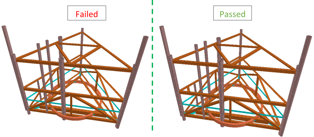
We investigated the effect of feeder arrangements on tower utilisation. We placed four antennas at the top of an existing 30m square lattice tower, fed by 16 typical sized feeders in a variety of different arrangements. To replicate a common tower arrangement, the structure also included a ladder mounted on one of the tower faces.

What We Found

Our analyses showed the maximum tower utilisation with the feeders stacked in a single row of 16, mounted on one leg, adjacent to the ladder location. Minimum utilisation was from feeders stacked in rows of four, mounted on a leg that is not directly supporting the ladder.

The difference in structural utilisation between these two scenarios was 15% for the tower legs, and 38% for the tower braces!

A surprising find was the structural utilisation from the feeders separated into groups of four, stacked in rows of two, mounted on each leg. The leg and brace utilisation were greater than those in the minimum scenario by 5% and 6% respectively.

Take Away Message

Feeders must be arranged with tower loading in mind. With less loading from feeders, more ancillaries can be placed on the tower, resulting in a more useful AND more financially profitable structure.

Check your existing towers. Check your proposed towers. Think about how the feeders are, or are proposed to be, arranged:

  • Are the feeders helping to distribute the loads more evenly throughout the tower?
  • Are the feeders stacked in the most efficient manner to reduce wind load on the structure?

KAEG continues to leverage our expertise to maximise the structural potential of your asset. Contact our expert team at: info@ka-engroup.com to learn more and discuss how we can best serve your needs.

Structural Analysis of a Tower Array

At KA Engineering Group, we recently completed a project involving the structural analysis of a sequence of towers supporting netting enclosing a sports complex to ensure that the structures could withstand the wind and weight loading on the, tower, connecting wires and netting, protecting the public from stray balls.

The towers are connected as an array, so it is important to analyse the full connected structure to properly define the system response. However, analysing a large number of lattice towers in a single finite element analysis is complex and computationally expensive. To simplify, we completed preliminary analysis by replacing the lattice towers with single poles. We had to ensure that the poles were representative of the global behaviour of the individual towers. The closer the poles are to the towers, the more analogous the global interaction between the actual tower sequence.

We determined the global properties such stiffness, deflection, of each individual lattice tower. The structural characteristics of the poles (main inner and outer diameters) were iteratively refined until the pole and lattice tower responses were equal. The benefit of continuous refinement is greater accuracy. Using the resulting loads (forces, moments) from the sequence analysis of the poles, we were able to assess then perform detailed analysis of each lattice tower.

Using poles in the sequence analysis allowed us to deliver the project in good time to the client. At KA Engineering Group, we continue to push boundaries, developing new and unique ways to tackle structural issues and advancements in a range of applications. The dynamic nature of the development in our company sets us apart from our competition as we are always seeking to improve existing methods.

Contact our expert team at: info@ka-engroup.com to learn more and discuss how we can best serve your needs.

Brace Supports for EMA Poles

In wall mounted pole structures, the design loads on ancillaries, i.e. wind load and vertical gravitational loads, are transferred to the walls through the anchors.The anchor pull-out load is limited by anchor and wall capacity. In the event of pull-out load being higher than anchor capacity, internal load bearing back plates can be installed. But if the pull-out load is higher than the wall capacity, a different strategy is adopted to redistribute the loads.

At KA Engineering Group, we have recently analysed and proposed diagonal bracing in wall mounted pole structures at two sites to reduce the cantilever overhang causing high anchor pull loads and posing risk to the primary structure (the wall). The braces are designed to reduce the dynamic loads on wall by redistributing the loads to rooftop. This design also optimises the primary pole and wall brackets and results in a cost-effective solution. If the primary pole is mounted near the corner of wall, the braces can also be installed to secondary wall mounted poles in two orthogonal directions.

KA Engineering Group not only completes structural due diligence for all telecommunication support structures, we also take further responsible steps to consider, advise, and optimise each site, ensuring cost effective design, installation, and maintenance for build contractors and efficient utilisation for operators.Contact our expert team at: info@ka-engroup.com to learn more and discuss how we can best serve your needs.
Tower Strengthening Project

At KA Engineering Group, we analyse a wide range of structures from monopoles to lattice towers and everything in-between. We recently completed the analysis of  an existing 48m tower for the proposed addition of a 2-meter microwave dish.

Using a combination of the information from previous site surveys, as-built construction drawings, and photographs, we produced a detailed 3D finite element model. We then applied wind, weight and ice loads based on British Standards and European Codes.

The tower had previously been strengthened through the addition of circular hollow sections (CHS) braces at various elevations. We found that these sections were themselves over-utilised and were adversely affecting the load distribution within the tower. As a result of this finding, the client was informed to remove the existing strengthening solution and to complete a more targeted strengthening scheme which brought the tower utilisation down to 80% providing more capacity for the future.

In addition to the strengthening solution analysis, we provided a general arrangement and fabrication drawing to clearly illustrate the sections that are to be replaced on the structure. KA Engineering Group not only completes structural due diligence for all telecommunication support structures, we also take further responsible steps to consider, advise, and optimise each site, ensuring cost effective design, installation, and maintenance for build contractors and efficient utilisation for operators.

Contact our expert team at: info@ka-engroup.com to learn more and discuss how we can best serve your needs.
Anchors Embedded in Masonry

In wall mounted pole structures, the function of anchor bolts is to transfer design forces such as uplift due to wind or vertical gravitational loads to the masonry. KAEG employs advanced engineering best practices to more consistently design and analyse anchors in order to ensure the installation properly embody its requirements.

The method of calculating the pull-out load is based on the shape of the failure surface, a truncated cone, observed during base material failure (Destructive loading). The proof test load is determined through structural analysis of two scenarios; wind perpendicular to wall and wind parallel to wall, taking ancillary orientation into account.

Anchors are tested (Non-destructive loading) with a pass result prior to installation to the calculated proof test load to confirms the holding power of anchors for the purpose of providing assurance of correct installation.

In the event that the calculated pull out load values is high, either load bearing internal back-plates or additional back-plated brackets are installed to strengthen the wall mounted connection, which negates the need to proof test the anchors.

Unlike concrete, masonry walls are not uniform base material and the location of the anchors in the wall affect the performance. Therefore, anchor designs require careful considerations in order to ensure that the applied loads are sufficiently distributed and the masonry is robust.

KAEG are at the forefront of providing valued engineering to achieve cost- and installation effective design solutions in the telecommunication industry to network providers. Contact our expert team at: info@ka-engroup.com to learn more and discuss how we can best serve your needs.

Freestanding Ballast Frames

The design of free-standing rooftop structure in accordance with design codes to serviceability criterion is a fundamental first principle design that can be completed by the old-school pen and calculator method, but the solution is often over- or under-designed. The designed solution must be adequate to ensure that the structure is stable against overturning moment (OTM) and sliding forces caused by wind action in addition to eccentric weights, accounting for the ancillaries, steelwork, and ballast frame.

Overturning moments are primarily due to wind forces in addition to eccentric vertical loads about the global centroid of structure. This de-stabilising load must be balanced and counteracted to achieve structural stability and safe operations.  More often, simplified method is adopted that only considers the destabilizing and stabilizing forces on one side of the structure which is not always the optimal design. Configuration optimisation is essential to achieve cost and installation effective solution such as reduced ballast frame size and induced pressure on the roof. This includes:

  1. Positioning the antennas and associated RRUs in a staggered configuration to reduce unfavourable eccentricity.
  2. Compact configuration which involve shielding the RRUs behind the antennas to reduce the wind destabilsing force.

KAEG are at the forefront of providing valued engineering to achieve cost- and installation effective design solutions in the telecommunication industry to network providers. Contact our expert team at: info@ka-engroup.com to learn more and discuss how we can best serve your needs.
Installation of Multiple Antenna Per Sector

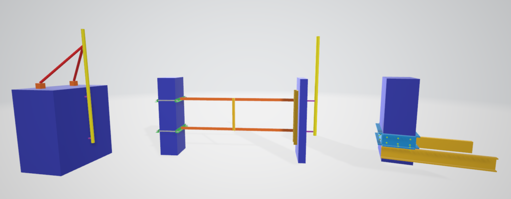
With increasing demand and fast changing technology, there is often a need to install two antennas in each sector to cover a large range of technology. Sometimes, there is enough space to install the antennas on separate primary poles, but often space is limited. For these cases, it is necessary to accommodate both antennas on a single primary pole with desired spacing to avoid clipping. There are two configurations available:

  1. Standoff system – One antenna on an offset pole using standoff bracket, and the other antenna on primary pole itself,
  2. Yoke system – Both antennae on offset poles using yoke bracket.

A standoff arrangement is often utilised when one antenna is an existing antenna and it belongs to another operator and hence it cannot be moved. However, it is an unfavourable arrangement.  Due to the antenna overhang on one side, the standoff system results in eccentric loading on the primary pole which requires bigger section to support. This also transmits higher bending loads on the primary structure.

A yoke arrangement is preferable as carries two antennae on either side of the primary pole. It can provide the desired spacing between the two antennas to avoid clipping, with less overhang. It also balances the wind load and weight from either side of the bracket and results in lower bending and torsional moments on the yoke bracket and primary pole.

This ultimately results in saving material by reducing the need to have bigger and stronger steel sections.

KAEG are at the forefront of providing cost-effective design solutions to over-stressed telecommunication structures to ensure continuous safe operations. Contact our expert team at: info@ka-engroup.com to learn more and discuss how we can best serve your needs.

Support Design for Cantilever Systems

Cantilever poles are used throughout the telecommunication industry to support ancillaries such as antennas and dishes. Frequently, the introduction of a proposed ancillary can exceed the capacity of the existing cantilever system, requiring new design requirements, new installations, and consequently, more money. There is a common misconception surrounding how to increase the capacity of a cantilever system.

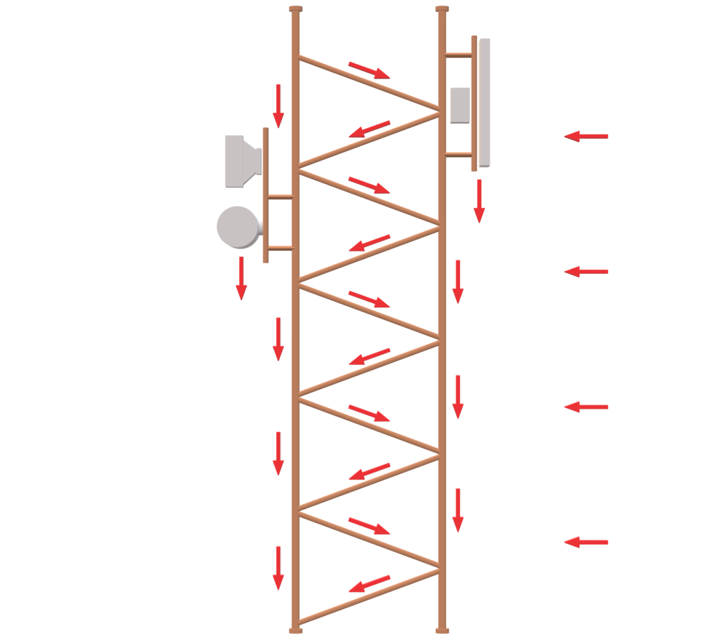
There are two ways in which cantilever systems are significantly loaded, they can either be shear-dominant or moment-dominant (shown below):

If the system is shear-dominant from the forces presented (i.e. the weight load is greater than the wind load), and the connections consist of two sets of two U-bolts, the bolts will be loaded in shear. For this condition, the greater number of bolts, the more secure the connection. However, in a moment-dominant system, the wind force has a greater effect on the system than the weight load, inducing a moment on the connections. In a moment-dominant system, the distance between the two sets of bolts (or “lever arm”) is the main influence.

If the moment induced on the system is anticipated to exceed the capacity of the existing bolt arrangement, placing a third bolt connection into the system between the existing bolt sets actually reduces the capacity of a moment-holding connection. This is because the lever arm length is reduced in the connection: from the distance between the upper and lower bolt sets, to the upper and central bolt sets.

To conclude, for a shear-dominant cantilever system, a third set of bolts is an appropriate solution. However, for a moment-dominant cantilever system, a better solution is to increase the distance between the existing bolt connections, increasing the capacity of the cantilever system.

KAEG are at the forefront of  providing cost-effective strengthening solutions to over-stressed telecommunication structures to ensure continuous safe operations.

Contact our expert team at: info@ka-engroup.com to learn more and discuss how we can best serve your needs.
KAEG – Promoting Staff Wellbeing

At KAEG we understand the value of our highly qualified and experienced engineering team. As such, we believe that staff well-being should take priority on our HR agenda. The 5 steps to positive mental well-being as suggested by the NHS: connecting with people, being physically active, learning new skills, giving to others and mindfulness – are embedded into our work environment and culture at KAEG.

It is undeniable that the option of working from home allows staff to stay very much connected with the people who matter most-their family. Our working arrangement takes away the stress and additional cost of childcare, with the flexibility to work successfully around family commitments. But whilst this is great for some, others might find the prospect of working from home an isolating experience. Our clever use of a virtual office, to compliment our working office, allows ongoing support and interaction throughout normal hours, so that no one ever feels alone. Additionally, company funded team-building retreats and activities, offered to all staff, have helped to build up strong relationships within our team. Our staff are very much connected with their colleagues from all over the world, and benefit massively from the strong support network.

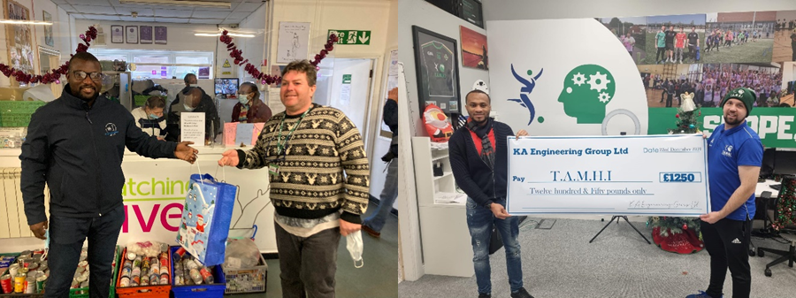
As our staff spend a lot of their working time in their home office, they are encouraged to keep fit outside of work. In general, it is argued that the main barriers to an active lifestyle are: cost, a lack of time, a lack of support and a lack of opportunities. KAEG breaks down these barriers. Working from home allows people to save a lot of wasted time, that many spend on a commute, opening up opportunities to access a range of different clubs and teams. The company even offer a monthly reimbursable contribution towards gym membership to all employees. The directors lead by example, sharing their incredible sporting feats, with Kingsley being voted by his team as football player of the year just last December.

Staff are actively encouraged to pursue their interests, learn new skills and give something back to others. Frequent review meetings allow staff to have their say in how they would like to grow and progress. Cost of relevant training courses are covered by the company, taking away an additional barrier to growth. Giving staff a certain autonomy in the areas in which they would like to specialise, creates greater engagement and motivation for progression. Within our company, knowledge is our most valuable resource and all staff are given numerous opportunities to share it. This might be through mentoring other members of the team, sharing their knowledge through writing blogs or technical papers and through giving technical presentations during training.

Every month, KAEG hosts a meeting for all staff where they can reflect on the challenges and the successes over the last month. It allows everyone the opportunity to discuss any challenges they may have faced and receive support from the whole team, allowing them to tackle these with a fresh outlook. More importantly, it encourages all to be mindful, to reflect on the present moment and take notice of how far they have come.

If you are interested in joining a company dedicated to promoting staff well-being, check out our current vacancies on indeed: Vacancies.

KAEG Values Talent

Meet Ellie, a full-time mum of two lovely kids who joined the KAEG team in the later half 2019. Ellie graduated with a degree in physics from Tehran University (2005), worked for a number of years before obtaining her Masters (MSc) in Advanced Engineering Design at Brunel University London (2018).

Like many full-time mothers, Ellie faced the challenge of putting her professional career on hold to raise her kids. As Ellie’s blessings grew, the gap in her career widened and it became increasingly difficult to transition back to full time employment.

During Ellie’s interview, one of her main worry was child-care and how to manage mum duties and work. However, the raw ability and diligence that Ellie displayed during the interview process was sufficient to convince KAEG management that she was the perfect fit for the business.

At KAEG, we believe in people oriented management. We strive to create an atmosphere where talent can be recognised irrespective of logistical obstacles. KAEG management fully appreciate and recognise that children are a blessing. By working with Ellie to organise and manage her time, she is able to enjoy her young family whilst building a career in a business that values her.

Ellie successfully completed her first internal progress review with excellent and constructive feedback for her good work. She is on her way to becoming one of telecom’s finest structural engineer.

Does cozaar cause hair loss Where to buy avapro online in Saskatoon Generic adcirca from Montreal Coreg 25 mg tablet Where to buy zyprexa 10mg online in Manitoba Buy casodex online from Boston