Overview of Telecom Support Structures

The ever-increasing demand for mobile telecommunication, radio, radar, and television communications means that more and more individuals (technical and non-technical) are encountering the telecoms industry. There is therefore the need for a simplified overview/general specification to provide internal and external stakeholders/investors, users, non-technical and technical professionals with the basic knowledge and understanding of telecoms structural engineering.

This post presents the various key classes of telecommunication support structures that are instrumental in the continued success of data transmission.

Self-Supporting Monopole Towers

Monopole towers comprise of constant tapered steel tubes or segmented tubular steel section that are welded or bolted to each other to form a pole decreasing in diameter from the bottom to the top. Sections are usually made from hollow, heavy duty, thick steel tubes, flanged steel tubes or low-alloy, high-strength steel, finished to meet required local aesthetics.


Self-Supporting Lattice Towers

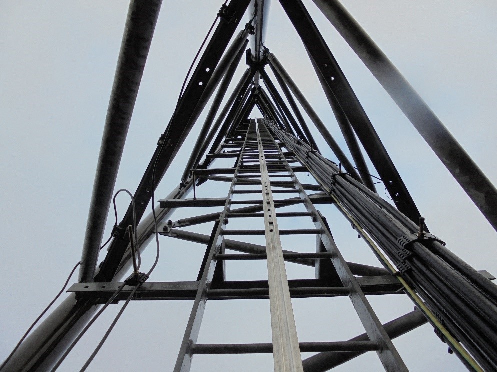
Self-supporting lattice also known as free-standing lattice tower structures consist of truss sections joined to form tapered or straight panel sections. The tapered panel sections have face width that vary according to height and load capacity. Lattice towers can have triangular (tripod) or square (quadpod) footprint. The truss members are commonly hollow tube, equal angle, or solid round bar. Although other section types such as folded (<90deg) steel angle are possible.


Guyed or Stayed Lattice or Monopole Towers

These are lattice or monopole towers similar in design to the self-supporting tower class except that they are further stabilised by tethered wire or rope systems. Guy wires are made from pre-stretched steel only and care must be taken to ensure that they are not be over tightened during installation and in-service to avoid misalignment, cable rupture and permanent wrapping of the tower structural members. Additionally, structural design of the guy anchor shall consider the nature and bearing capacity of the soil.


Roof and Wall Elevated Mounts

Roof and wall elevated mounts can be an inexpensive way of elevating signals above roof interference or other obstructions by mounting the equipment atop an already high and stable structure (e.g. rooftop of a high-rise building). Roof mounts can be penetrating (impacting) or non-penetrating (non-impacting) installations and can also be self-supporting or guyed. In all cases, structural checks and certification by competent engineering team must be made to establish the capability of the roof to withstand the additional imposed loads due to the proposed ancillaries and steelwork installations.


KA Engineering Group does not only complete structural due diligence for all these telecommunication support structure classes, we also take further responsible steps to consider, advise, and optimise each site, ensuring cost effective installation and maintenance for build contractors and efficient utilisation for operators.

Contact our expert team at: info@ka-engroup.com to learn more and discuss how we can best serve your needs

Assessment of Ageing Riser Conductor

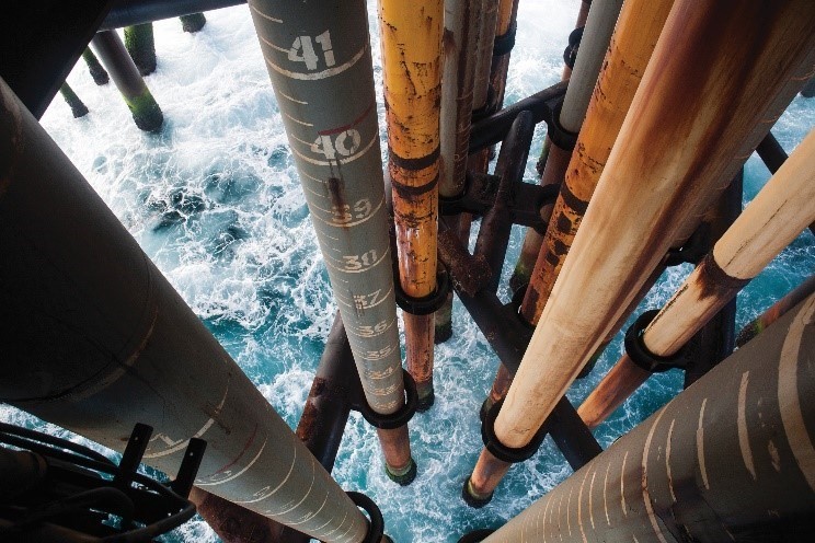
The oil and gas industry are faced with mature platforms in the North Sea, Middle East, Africa, and other areas of the world which are in their latter stages of design life or have already exceeded their design life. In-service assessment of these ageing riser conductor system condition is important to ensure safe continuous operations, enhance confidence, recommend and carry out strengthening analysis and design of these structures with the aim of extending their original design life.

Engineering assessment of ageing riser conductor considers the original design including forecast environmental and operational loads, materials degradation and losses due to corrosion and erosion and operations induced stresses. In addition to determined degradation and losses, hindcast actual environmental and operational loads are used to establish the riser conductor capacity utilisation to-date, and this is compared and bench-marked against the original design capacity to determine the remaining utilisation and remaining useful life, if any. Possible outcome includes:

  • There is sufficient remaining design structural capacity for safe continuous operations – considering routine and improved recommended maintenance and inspections, predict the asset safe remaining in-service useful life;
  • There is marginal or no useful design structural capacity to ensure safe continuous operations – complete effective strengthening design and recommendations to extend and predict the useful design life for safe continuous operations;
  • Useful design structural capacity has been exceeded – complete effective repair and strengthening design and recommendations to extend and predict the useful design life for safe continuous operations.

Engineering assessment of riser conductor can be a cost-effective structural integrity tool not only for ageing high risks riser conductor systems but also for immature low risks subsea well platforms, to avoid the problems and unplanned expensive repairs and loss of assets suffered by ageing platform facilities.

Contact us to learn more and discuss your needs with our expert team and how we can best serve: info@ka-engroup.com

Effects of Feeders Arrangement

The exponential growth in the use of cellular phones and the need for effective radio, radar, and television communications has increased the demand for new era taller towers and masts with capacity to accommodate even more ancillaries. These tall structures must be able to primarily withstand site-specific environmental natural loads such as wind and ice, in addition to axial forces. These tall slender structures are not without engineering challenges such as optimising the structure arrangement, members size, installation and maintenance considerations, connections and foundations, and most importantly available non-utilised capacity for the installation of antennas, dishes, and other communication ancillaries. These challenges are further exacerbated for guyed masts but may in some cases be the efficient solution to be adopted. Although guyed mast comes with several benefits including increased capacity, it is one of the most complicated telecommunications structures to engineer.

Telecommunication tower and mast are dynamic sensitive structures designed to withstand onerous natural and imposed loads. In addition to the inherent complexity in the structural systems, the predominant loads of towers and masts are the environmental wind and ice loads, responsible for detecting the structural behaviour and dynamics of the structure. The dynamic behaviour of tower and mast can change significantly in the presence of ice which increases the axial load and most importantly, increases the wind drag of the tower and mast.

Engineering is unable to control the presence of ice and wind; however, efficient engineering can lead to reduced ice thickness on structure and the corresponding windage area. In other to achieve reduced windage loading area, it is important to understand the effects of ancillaries loading and arrangement. The overall layout of the telecommunication towers and masts are often governed by the requirements for transmission and receiving conditions usually defined by operators. Furthermore, the effects of feeders’ arrangements and installation location cannot be over-emphasised, and this is often overlooked or ignored during designs, and even more during Global Design Checks (GDC) of existing structure capacity for proposed and future technology upgrade installations. Inefficient feeders’ arrangement and installation location can cost site owners more than 25% tower and mast useful utilisation capacity which would have been used to accommodate more antennas, dishes, RRUs, etc.

KA Engineering Group does not only complete structural due diligence, we take further responsible steps to consider, advise, and optimise each site, ensuring cost effective installation and maintenance for build contractors and efficient utilisation for operators.
Contact us to learn more and discuss your needs with our expert team and how we can best serve: info@ka-engroup.com