From Cell Towers to Code: Merits of Software Engineers in Telecoms teams

To remain competitive in the changing business landscape, Telecoms structural engineering firms recognise the value of incorporating software engineers into their teams. Here, we explore some advantages of this approach, examining how software engineers can enhance the effectiveness of structural engineering teams.

  1. Automation of repetitious tasks for structural design: In Telecoms, different structure types come with varying number of configurations for their design that trying to keep track with them manually can be strenuous for structural engineers. With software engineers in the team, managing these configurations can be automated with software to aid in increasing the user’s productivity.
  2. Design of bespoke in-house software; technical and non-technical: While the main line of business may be building engineering models, having personnel on hand to build in house applications for tasks like those administrative in nature, or even technical ones like in design results report formatting tools can be advantageous to the firm.
  3. Working on cutting edge future technology to make the business ready to take advantage: Research and development of new technology can be more efficient when structural and software engineers are working in the same team. An example of this is the development of technology that uses LiDAR drones for modelling and analysis of structures. Software engineers working on the project can write programs on reconstruction of 3D models of structures from the drones, while Structural engineers in the team can aid in discarding outliers in generated models through their knowledge of what dimensions a structure of that nature can have realistically.

In summary, this interdisciplinary approach makes it easier to meet growing demands for reliable network infrastructure. At KA Engineering Group, our expert team does not just build precise models of engineering configurations, we partner with our clients in highlighting findings and providing detailed analysis reports. Contact us at: info@ka-engroup.com  to learn more and discuss how we can best serve your needs.

Streamlining Telecom Structure Surveys with Lidar Technology

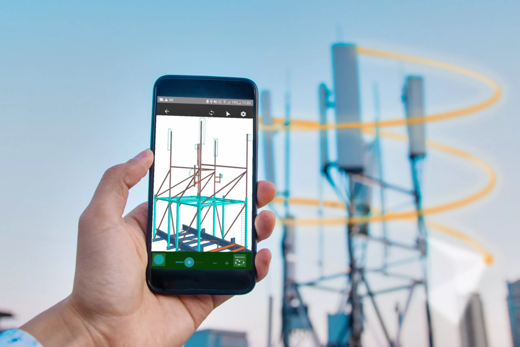
In the realm of telecom infrastructure development, precision and efficiency are paramount. Traditional methods of surveying telecom structures have undergone a revolutionary transformation with the advent of Lidar technology. Lidar, which stands for Light Detection and Ranging, utilises laser beams to measure distances and create detailed 3D models of objects and environments. While previously used primarily in specialised equipment, recent advancements have seen Lidar technology integrated into consumer devices, such as smartphones. Lidar, integrated into smartphones like recent iPhone models, enables capturing precise 3D models of objects.

Gone are the days of cumbersome on-site visits with dedicated cameras or expensive drones. With Lidar-equipped smartphones, surveyors can quickly capture intricate details of structures from a distance. The ability to generate detailed 3D models allows designers to gain a comprehensive understanding of the existing structure, eliminating the need to sift through countless photos, and hoping the surveyor did not miss a crucial angle or having to rely on guesswork.

Lidar technology in smartphones offers a cost-effective and accessible solution for surveying. Surveyors can efficiently capture and analyse data, reducing time and expenses. Portable and versatile, these devices adapt to various environments, from remote cell towers to urban infrastructure.

In conclusion, Lidar technology in smartphones streamlines surveying, enhances accuracy, and provides valuable insights into existing structures. As technology advances, further innovations will revolutionise telecom infrastructure development, making surveying tasks more efficient than ever.

Failure modes of fasteners in concrete

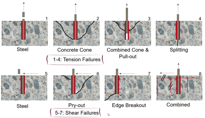
Failure modes of anchor fasteners refer to the different ways in which fasteners can fail when used in concrete structures. These modes can be categorised as failure of anchor (steel) or the parent material (concrete). These can also be categorized as tension, shear or combined failure, as shown in the attached image.

Here are some common failure modes:

  • Bolt Tensile Failure: This occurs when the tensile strength of the bolt is exceeded, causing it to break or fracture under tension.
  • Concrete Cone Failure: This occurs when the concrete surrounding an anchor fails, typically in a cone shape.
  • Pullout Failure: In this mode, the fastener is pulled out of the concrete due to the tensile forces when the bond between the fastener and the concrete is not strong enough.
  • Concrete Splitting: This occurs when the concrete itself splits or cracks due to the applied forces, causing the fastener to lose its grip or become ineffective.
  • Steel Failure: This occurs when the fastener itself, typically made of steel, fails due to shear stress exceeding its strength. The fastener may fracture or deform, leading to loss of load-carrying capacity.
  • Concrete Pryout: This occurs when the fastener pulls out or displaces the concrete around it. This failure mode is more likely to happen when the fastener is located near the edge of the concrete element.
  • Concrete Breakout: This occurs when the concrete surrounding the fastener fails in shear. It occurs when the applied shear force causes the concrete to crack or break, resulting in the loss of anchorage.
  • Combined Failure: This is a combination of shear and tensile failure. It happens when the bond between the fastener and the concrete is not strong enough to resist the applied shear force, causing the fastener to be pulled out of the concrete.

It is important to consider these failure modes when designing and installing fasteners in concrete structures to ensure their proper performance and safety. At KA Engineering Group, we leverage on our extensive experience to design and recommend most efficient fastening solutions for new as well as existing systems in telecom construction.

Contact our expert team at info@ka-engroup.com to learn more and discuss how we can best serve your needs.

Why do we need Foundation Strengthening?

The ever-increasing demand for better connectivity means a constant upgrade of the telecommunications network. Put simply, the number of antennas and their sizes are increasing. Practically, this means existing infrastructure, such as towers, needs to support heavier and heavier loads.

In previous blogs, we have touched on tower strengthening to improve capacity. However, what happens when the limiting component is the sub structure (foundation). Take a typical pad foundation for a tower, it was sized for a particular load, cast, and then buried under the ground. What happens when this load capacity is exceeded? Do we just abandon the upgrade?

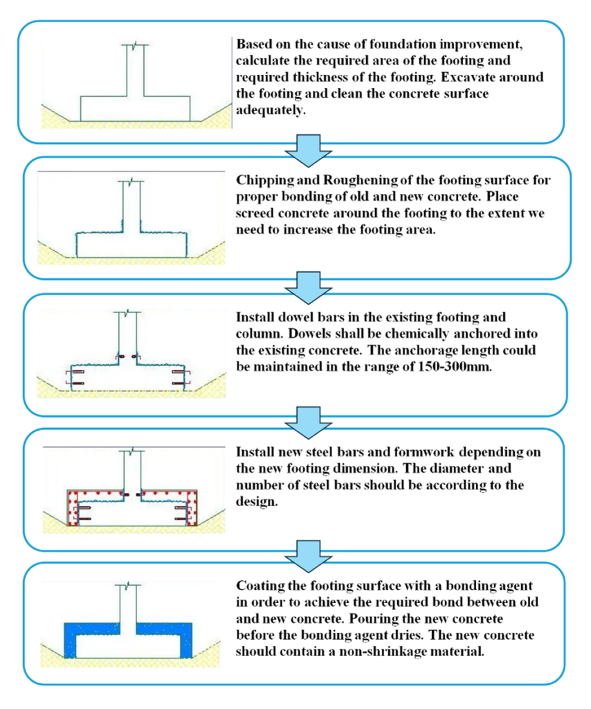
Can the foundation capacity be increased? The answer to this is a resounding Yes! There are a few ways to increase the stabilization capacity of a pad foundation. The commonest way is through foundation extension, the steps of which we have roughly shown in image attached to this post.

At KA, we have the expertise to design the foundation extension to accommodate your proposed upgrade. We complete stability and bearing checks, dowel calculations and provide reinforcement drawings for the foundation extension. Contact our expert team at: info@ka-engroup.com to learn more and discuss how we can best serve your needs. 

Elastic Instability – Buckling

For telecommunications structures, members in compression play a significant role in the overall structural behaviour. Such members are often seen in lattice towers, monopoles, tripod and quadpod braces, and ancillary support poles. Therefore, examining buckling, a standard failure mode of such elements, is always pertinent.

Buckling, a major type of instability refers to the sudden loss of stiffness at a critical load, which results in deflection to a side. Such deflections can result in material inelasticity and large deformations, leading to an unstable structure and collapse.

The various structural design codes such as AISC and Eurocodes rely on general ideas from Euler’s buckling formula to calculate strength reduction factors buckling evaluation. Eurocodes, for instance, require the calculation of a non-dimensional slenderness constant, which is then used in established buckling curves for strength reduction factors determination.

 In the event of buckling design failure, we try methods of reducing effective length (mostly by reducing the unbraced length), increasing the sectional area or steel grade and finding ways of reducing load distribution to the concerned member. Since buckling failure can be catastrophic, care must be taken to ensure proper analysis and design are done to prevent avoidable structural failure.

At KA Engineering Group, we leverage our extensive engineering experience to accurately design any form of telecoms structure ranging from complex GDC to basic DD analysis. We take responsible steps to consider, advise, and optimise each site, ensuring cost-effective design, installation, and maintenance for build contractors and efficient utilization for operators. Contact our expert team at: info@ka-engroup.com to learn more and discuss how we can best serve your needs.