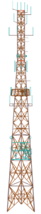
 At KA Engineering Group, we analyse a wide range of structures from monopoles to lattice towers and everything in-between. We recently completed the analysis of an existing 48m tower for the proposed addition of a 2-meter microwave dish.
Using a combination of the information from previous site surveys, as-built construction drawings, and photographs, we produced a detailed 3D finite element model. We then applied wind, weight and ice loads based on British Standards and European Codes.
The tower had previously been strengthened through the addition of circular hollow sections (CHS) braces at various elevations. We found that these sections were themselves over-utilised and were adversely affecting the load distribution within the tower. As a result of this finding, the client was informed to remove the existing strengthening solution and to complete a more targeted strengthening scheme which brought the tower utilisation down to 80% providing more capacity for the future.
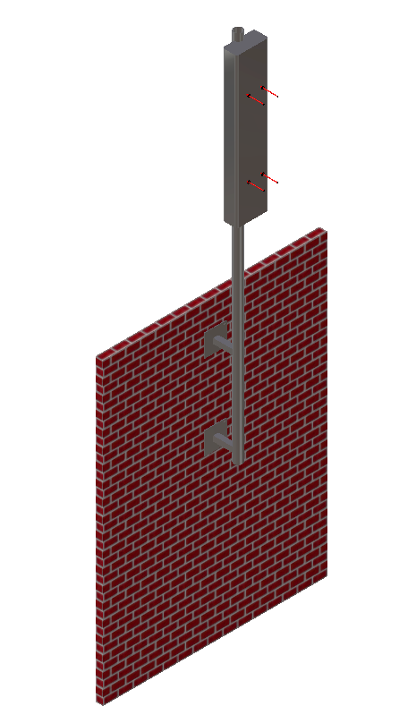
In addition to the strengthening solution analysis, we provided a general arrangement and fabrication drawing to clearly illustrate the sections that are to be replaced on the structure. KA Engineering Group not only completes structural due diligence for all telecommunication support structures, we also take further responsible steps to consider, advise, and optimise each site, ensuring cost effective design, installation, and maintenance for build contractors and efficient utilisation for operators.
Contact our expert team at: info@ka-engroup.com to learn more and discuss how we can best serve your needs.