Can you make a telecommunications structure disappear? The answer is yes!
Telecoms equipment isn’t always the most discreet addition to a building. Whether it’s to satisfy planning regulations, reduce visual impact, or protect sensitive equipment, shrouds/screens can play a crucial role.
But not every site needs a shroud. So, when is it the right time to use one?
There are a few reasons for why you would want to install a shroud/screen around telecoms equipment.
Maybe you want to hide an unsightly pre-existing steel structure for aesthetics or planning permission that require concealment? There are various local authorities that demand telecoms equipment to be concealed to minimise visual impact. This can help blend the equipment into the surrounding environment and most of the time you can even colour match these screens to suit the building or streetscape.
Other reasons are based on durability and protection against environmental factors. Shrouds can offer protection against UV light, rain and corrosion, thereby extending the life span of the telecom equipment because it is a shield from direct exposure.
Now you know at what times you could consider using shrouds, but what material is most effective?
In recent years, fiber-reinforced polymer (FRP) or glass-reinforced polymer (GRP) has become a preferred choice of material in the telecommunications industry due to its corrosion resistance, high strength and lightweight properties. Most importantly, FRP/GRP is a suitable material where electromagnetic interference (EMI) or radio frequency interference (RFI) is a cause for concern. FRP/GRP is most likely the best material to use for shrouding as it can be produced in a range of colours and components can be moulded into specific shapes, all of which help to improve the aesthetic of the building.
Can you just install a shroud/screen around the telecommunications equipment in your building? I am afraid but the answer is not that simple.
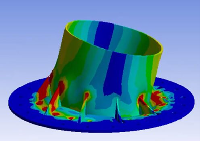
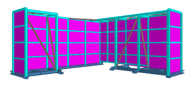
In conclusion, shrouds are best used when aesthetics, planning compliance, RF transparency, and durability are required, it is still essential to have a competent engineer certify their suitability, particularly when they are fixed to the supporting structure. Due to their large surface area, shrouds can attract significant wind loads, which increase the forces acting on the structure. A competent engineer must therefore assess and confirm that the telecommunication structure can safely withstand these additional loads. Contact our expert team at: info@ka-engroup.com to learn more and discuss how we can best serve your needs.