Failure modes of fasteners in concrete

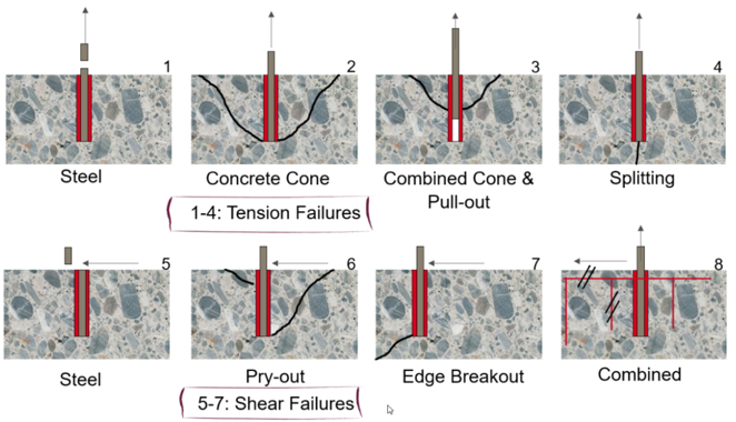
Failure modes of anchor fasteners refer to the different ways in which fasteners can fail when used in concrete structures. These modes can be categorised as failure of anchor (steel) or the parent material (concrete). These can also be categorized as tension, shear or combined failure, as shown in the attached image.

Here are some common failure modes:

  • Bolt Tensile Failure: This occurs when the tensile strength of the bolt is exceeded, causing it to break or fracture under tension.
  • Concrete Cone Failure: This occurs when the concrete surrounding an anchor fails, typically in a cone shape.
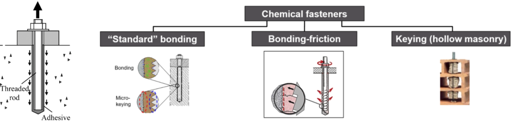
  • Pullout Failure: In this mode, the fastener is pulled out of the concrete due to the tensile forces when the bond between the fastener and the concrete is not strong enough.
  • Concrete Splitting: This occurs when the concrete itself splits or cracks due to the applied forces, causing the fastener to lose its grip or become ineffective.
  • Steel Failure: This occurs when the fastener itself, typically made of steel, fails due to shear stress exceeding its strength. The fastener may fracture or deform, leading to loss of load-carrying capacity.
  • Concrete Pryout: This occurs when the fastener pulls out or displaces the concrete around it. This failure mode is more likely to happen when the fastener is located near the edge of the concrete element.
  • Concrete Breakout: This occurs when the concrete surrounding the fastener fails in shear. It occurs when the applied shear force causes the concrete to crack or break, resulting in the loss of anchorage.
  • Combined Failure: This is a combination of shear and tensile failure. It happens when the bond between the fastener and the concrete is not strong enough to resist the applied shear force, causing the fastener to be pulled out of the concrete.

It is important to consider these failure modes when designing and installing fasteners in concrete structures to ensure their proper performance and safety. At KA Engineering Group, we leverage on our extensive experience to design and recommend most efficient fastening solutions for new as well as existing systems in telecom construction.

Contact our expert team at info@ka-engroup.com to learn more and discuss how we can best serve your needs.

Why do we need Foundation Strengthening?

The ever-increasing demand for better connectivity means a constant upgrade of the telecommunications network. Put simply, the number of antennas and their sizes are increasing. Practically, this means existing infrastructure, such as towers, needs to support heavier and heavier loads.

In previous blogs, we have touched on tower strengthening to improve capacity. However, what happens when the limiting component is the sub structure (foundation). Take a typical pad foundation for a tower, it was sized for a particular load, cast, and then buried under the ground. What happens when this load capacity is exceeded? Do we just abandon the upgrade?

Can the foundation capacity be increased? The answer to this is a resounding Yes! There are a few ways to increase the stabilization capacity of a pad foundation. The commonest way is through foundation extension, the steps of which we have roughly shown in image attached to this post.

At KA, we have the expertise to design the foundation extension to accommodate your proposed upgrade. We complete stability and bearing checks, dowel calculations and provide reinforcement drawings for the foundation extension. Contact our expert team at: info@ka-engroup.com to learn more and discuss how we can best serve your needs. 

Elastic Instability – Buckling

For telecommunications structures, members in compression play a significant role in the overall structural behaviour. Such members are often seen in lattice towers, monopoles, tripod and quadpod braces, and ancillary support poles. Therefore, examining buckling, a standard failure mode of such elements, is always pertinent.

Buckling, a major type of instability refers to the sudden loss of stiffness at a critical load, which results in deflection to a side. Such deflections can result in material inelasticity and large deformations, leading to an unstable structure and collapse.

The various structural design codes such as AISC and Eurocodes rely on general ideas from Euler’s buckling formula to calculate strength reduction factors buckling evaluation. Eurocodes, for instance, require the calculation of a non-dimensional slenderness constant, which is then used in established buckling curves for strength reduction factors determination.

 In the event of buckling design failure, we try methods of reducing effective length (mostly by reducing the unbraced length), increasing the sectional area or steel grade and finding ways of reducing load distribution to the concerned member. Since buckling failure can be catastrophic, care must be taken to ensure proper analysis and design are done to prevent avoidable structural failure.

At KA Engineering Group, we leverage our extensive engineering experience to accurately design any form of telecoms structure ranging from complex GDC to basic DD analysis. We take responsible steps to consider, advise, and optimise each site, ensuring cost-effective design, installation, and maintenance for build contractors and efficient utilization for operators. Contact our expert team at: info@ka-engroup.com to learn more and discuss how we can best serve your needs.

Rigger Safety in Telecom Structural Design

A common pitfall in telecoms structural design is to solely consider the proposed structure from the viewpoint of the ancillary (antennas/dishes) operability. This is natural, after all, functioning ancillaries are what make money. However, it is very important to not forget the human element. These ancillaries must be installed/rigged by real people who need to return home safely.

A rigger anchoring to a piece of telecom steelwork effectively puts their lives in the hands of the structural designer. This responsibility should not be taken lightly. Accidental loads in all their various forms must be carefully considered throughout the design phase. Engineers can uphold their ethical responsibility and help to create a safer working environment for employees who construct and maintain these essential telecommunications facilities by prioritising safety during the design phase.

At KAEG, safety is part of our core values, it is a philosophy that underpins everything we do. Our structural teams have real site/ climb experience which allows us to put ourselves in the rigger’s position so we can even sense check “attractive nuisance” steelwork that the rigger is not “supposed” to anchor to.

Stay safe out there and reach out to our expert team at: info@ka-engroup.com to see how we can best serve your needs.

Drone Surveys: Taking Telecoms Structural Engineering to New Heights

Drone surveying is the use of unmanned aerial vehicles (UAV) equipped with specialized cameras to capture aerial data. It has had a positive impact on the way telecoms structural engineers now approach design, maintenance, and optimisation of telecoms structures from previous traditional methods. Here are some intriguing benefits of this innovation:

  • Seamless Integration with Data Analysis tools: With modern advances in technology and the abundance of data collected during drone surveys, captured images can be transferred to data analysis and modelling tools. Engineers can then create accurate simulations to anticipate the effects of loads on the structural integrity of telecoms infrastructure.
  • Cost-Saving: Drone surveys can reduce manual labour costs and can result in more efficient resource allocation.
  • Virtual Inspections: 3D models can be constructed from sensors like UAV LiDAR sensors, enabling more immersive inspections and minimising safety risk for the engineers on site

In essence, drone surveying is likely to become a quintessential technique for inspecting modern telecoms structures. We are sure the conversation around there use will continue to grow, At KA Engineering Group, we take a responsible approach to considering, advising, and optimizing each site, ensuring cost-effective design, installation, and maintenance for build contractors and efficient utilization for operators. Contact our expert team at: info@ka-engroup.com to learn more and discuss how we can best serve your needs.

Mastering the Craft

Last week, we shared with you a glimpse into the diverse range of structural solutions that KAEG offers; from rooftop scanning to tower mapping. Our mission is to simplify and remove barriers, providing you with comprehensive structural services. As we continue our journey, let us delve deeper into the importance of specialisation and how it defines our approach at KAEG.

In the past, we have been asked why we do not dabble in CAD drawings or other related areas. As the saying goes, “Jack of all trades, master of none.” At KAEG, we firmly believe that true expertise comes from a dedicated focus. Just as our previous blog highlighted our commitment to solving structural challenges, specialisation has been our guiding principle to achieve mastery in our field.

While we specialise in structural services, we also recognise the value of collaboration. Instead of trying to cover all bases, we have forged partnerships with experts in various fields. We embrace the concept of tapping into the strengths of others when it complements the vision and objectives of a project. This strategic approach allows us to deliver exceptional results by harnessing the collective expertise of our extended network. These collaborations also enable us to offer you a complete and seamless package, maintaining the highest standards throughout the project lifecycle.

At KAEG, specialisation is not just a buzzword; it is a philosophy that underpins everything we do. Our commitment to mastering structural-related services and building a network of experts has proven to be the cornerstone of our success. As we embark on each project, we remain dedicated to the art of specialisation, ensuring that we deliver solutions that are unparalleled in quality. We invite you to continue on this journey of excellence with us, where specialisation meets collaboration, and expertise knows no bounds.

For further insights or to discuss your unique project needs, please reach out to our expert team at: info@ka-engroup.com. Together, let us build a future that is not only structurally sound but also truly extraordinary.

Chemical fasteners

A short discussion on chemical fasteners, continuing our series of posts on fastening technology. Chemical fasteners transfer tension load to the borehole mainly via adhesion. The components are connected to one another to form an adhesive bond.

Advantages:

  • ​​​​​​​High load-carrying capacities
  • No expansion forces (ideal for fastenings near the edge)
  • Suitable for anchoring in solid and hollow building materials (hollow building materials require a mesh sleeve)
  • Sealing function

Limitations:

  • ​​​​​​​No immediate load-carrying capacity (curing times)
  • Special assembly requirements:
  • Thorough borehole cleaning (prevent high load-bearing capacity losses)
  • Components must be mixed completely
  • Processing and ambient temperatures affect the curing time
  • ​​​​​​​Special storage requirements:
  • Storage period
  • Heat sensitivity

We will discuss more on failure modes of fasteners in subsequent blogs. Stay tuned.

At KA Engineering Group, we leverage on our extensive experience to design and recommend most efficient fastening solutions for new as well as existing systems in telecom construction.

Contact our expert team at info@ka-engroup.com to learn more and discuss how we can best serve your needs.

Don’t Forget Primary Structure Check for Rooftop Stub Towers

Rooftop stub towers, a solution that has gained popularity for its ability to overcome space constraints and improve connectivity in urban environments. When performing structural analysis on stub towers, it’s easy to focus solely on the tower structure, headframe and secondary steelworks. However, it’s crucial not to overlook the primary structure of the building itself.

The primary structure of a building supports the weight of the entire structure, including the added load of a rooftop stub tower. Conducting a load-bearing capacity assessment is crucial to ensure that the building’s structure can safely accommodate the additional weight and forces imposed by the tower and its equipment. This assessment involves evaluating the roof slab, columns, beams, and other structural elements to determine their ability to bear the load without compromising structural integrity. A thorough structural analysis can also help to determine how the additional weight and forces from the rooftop stub tower are distributed within the primary structure. By assessing load distribution, engineers can identify areas that may require reinforcement or modifications to maintain the stability of the primary structure under varying conditions.

Also, adhering to building codes and regulations is of utmost importance when designing rooftop stub towers. Building codes often outline specific requirements for structural integrity, load capacities, and safety factors. KA Engineering Group possess extensive knowledge and experience during the completion of hundreds of stub tower projects to assess the stub tower and building’s structural capacity.

Contact our expert team at: info@ka-engroup.com to learn more and discuss how we can best serve your needs.

EMA Strengthening Solutions

EMA Poles are common telecom structures in city centres. EMA poles are usually held by standoffs attached to a plate and connected to a wall through anchor bolts. The forces generated causes the anchors to want to pull out from the wall. Historically, these anchors are held by chemical resins injected into the wall. Click here for description of chemical resin anchors. Usually, where the pull out load is excessive, the resin anchors become unsuitable to resist pull out and strengthening solutions needs to be adopted where the EMA is existing. There are two possible strengthening solutions

Back plating: This involves using a bolt that passes through the wall to the other end held by a back plate. In this case, pull out of the bolt is resisted by the rigid connection of the plates and nuts at the back. For the bolts to pull-out, the entire wall will have to cave in. Hence, the proposal of a back-end plate negates the need to pull test the anchors.

Over plating: This involves increasing the number of bolts and spacing of the existing anchors. A small Equal angle (EA) steel section is placed over the existing front plate and new bolt holes are drilled at the top and bottom of the EA for new bolts to pass through the wall. This increases the number of bolts and hence reduces the pull-out force as the forces are shared by 6No. bolts as opposed to 4Nos as shown in the fig 2b below.

Lattice Tower Braces

Lattice towers can be braced in various configurations (see image) but have you ever wondered why a particular configuration is selected?

Braces are needed to keep a structure stable and prevent it from swaying or drifting since most towers act as a cantilever system. They transfer lateral loads from the tower to the ground and they also prevent the tower legs from buckling. There are various types of brace configurations but can be broadly simplified to 3 groups.

Configuration 1 is called a Single brace and they are good for resisting light loads for instance near the top of a tower.

Configuration 2 is called a Cross Brace and is capable of withstanding both tensile loads and drifts.

Configuration 3 is called a Chevron/K- Bracing and it is used for controlling deflection and resisting lateral loads.

Other brace configurations are made from a combination of these basic configurations.

At KA we ensure that the right brace configuration is selected to new tower design or applied for strengthening scheme to increase capacity to withstand lateral loads. We also take responsible steps to consider, advise, and optimise each site, ensuring cost-effective design, installation, and maintenance for build contractors and efficient operator utilisation. Contact our expert team at: info@ka-engroup.com to learn more and discuss how we can best serve your needs.