Cracked and Uncracked Concrete in Anchor Calculation

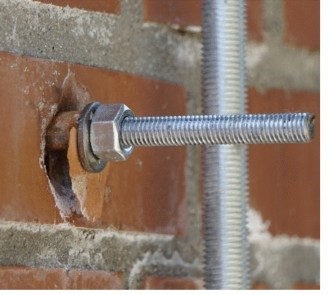
The choice of anchor and the method used to calculate its capacity are essential for a successful installation. One critical factor in anchor calculation is the condition of the concrete into which it is installed. Concrete can be either cracked or uncracked, and this distinction significantly impacts anchor performance.

Cracked vs. Uncracked Concrete

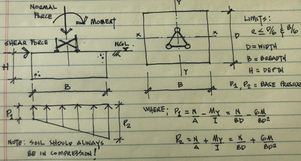
Uncracked concrete is where the tensile stress in the concrete is smaller than the tensile strength of the concrete.

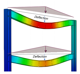
Cracked concrete will be seen on reinforced-concrete members under service conditions and in the tension zone.

 Concrete is typically assumed to cracked under normal service load conditions, but when can it be assumed to be uncracked?

Design for uncracked concrete conditions is permitted only when the designer can demonstrate with stress analysis that the concrete around the vicinity of the anchor, will remain uncracked throughout its service life in all future loading conditions. This is typically only the case in members or parts of members which will not experience significant tensile forces.

Conclusion

Distinguishing between designing fasteners for cracked or uncracked concrete is crucial for ensuring the structural integrity and safety of anchors. It is important to follow the codes and standards meticulously when designing and installing these anchors.

Limitations of Structural Models

“All models are wrong, but some are useful”. This aphorism coined by George Box for statistical models may also have a grain of truth about structural models. Often in telecoms structural analysis, assumptions are made to simplify the calculation process or fill in for missing data. A good engineer will ensure that these assumptions are based on sound theory and perhaps even well-established industrial design codes. However, engineers must take care to be aware of the limitations of the any assumptions employed.

As an example, analysis of telecoms structures is based on a static model, that is, checking that the structure survives under the action of an extreme load e.g., a 50-year wind event. Implicit in this design methodology is that fatigue failure is not an issue. Fatigue is the failure of a material under repetitive or cyclic loads at load significantly below loads that would cause yield: think about bending a paper clip back and forth, eventually it will snap.

There are certainly cyclic loads to consider for telecom structures: the wind is not constant; it changes direction and strength. So why do we not perform fatigue analysis for these structures? Well, the steel sizes used for telecoms structures would take a very long time to fail under fatigue for the typical cyclic stresses that they experience so fatigue is not a practical consideration. But is this true for all the components?

Consider a wall mounted antenna fixed to a brick wall by a chemical anchor (these terms should now be familiar to you from our previous blogs 😊). There are several components in that system that can experience rapid fatigue failure. Currently, it may not be practical to conduct fatigue analysis for these components, but this is where it is important that an engineer understands the limitations of the analysis model used.

For these wall anchors, we recommend that site providers and operators have a clearly defined integrity monitoring procedure for inspecting the anchors to ensure that they are still fit for purpose. The consequence of not doing this is that a day will come when you may simply be able to remove the anchor by hand! Even worse still, you may find the EMA on the ground which does not bear contemplating in a busy town centre.

Contact our expert team at: info@ka-engroup.com to learn more and discuss how we can best serve your needs.


Deflection in Telecom Structure Analysis

Deflection in telecommunication structures refers to the deformation or displacement of a structure from its original position under load. Deflection is a serviceability limit, that is, it does not automatically constitute structural failure, thus there are often differing requirements on the acceptable levels of deflection. There are typically two categories of deflection limits considered in telecoms analyses: General structural deflection limit and Operator’s deflection limit.

The operator’s deflection limit is specified by the site operator in the telecoms industry. They specify levels above which the structure becomes unfit for use based on ancillary equipment operational guidelines and specifications.

The general structural deflection limit is specified by design codes e.g., Eurocode & BS code an offers guidance on the level of deflection that will not cause discomfort/alarm to the site users.

The operator’s deflection limit can be a little generous. We often find that a structure can be within it operator’s limit but has exceeded its general deflection limit, therefore a decision must be made. Designing a structure that is below the general structure deflection limit may incur additional costs which the site operator may be opposed to. It is responsibility of the engineer to ensure that all stakeholders participate in the decision making and to balance the interest of all parties.

At KA Engineering Group, we leverage our extensive engineering experience to accurately design any form of telecoms structure ranging from complex GDC to basic DD analysis. We take responsible steps to consider, advise, and optimise each site, ensuring cost-effective design, installation, and maintenance for build contractors and efficient utilisation for operators.

Contact our expert team at: info@ka-engroup.com to learn more and discuss how we can best serve your needs.

Foundation Design for Telecom Structures

Telecom structures impose various actions on foundations and these foundations are to be designed by a competent structural engineer to resist these actions. Loads from superstructures (lattice tower, monopoles etc.) are transferred to the supporting foundation and eventually to the underlying soil. There are two broad categories of foundations: shallow and deep foundation. Let’s focus on shallow foundations for now e.g. isolated pad, combined footing, strip and mat foundations. There are three critical checks: bearing check, sliding check and overturning checks.

Bearing Check: the bearing pressure under the base area of the foundation should not exceed the safe (or allowable) bearing pressure of the soil. A geotechnical survey is required to ascertain the soil bearing pressure and other soil parameters.

Sliding Checks: the shear reaction from the telecoms base reaction could cause the foundation to slide. The design sliding factor is checked against the allowable sliding factor of safety

Overturning Checks: the foundation needs to be checked for overturning. Moment reactions from telecom structures could cause the entire system to overturn. For stability of the foundation, we need to check the design overturning moment factor of safety against the allowable overturning moment factor of safety.

It is essential that an existing or a proposed foundation be designed by a competent structural engineer. KAEG are at the forefront of providing cost-effective foundation design solutions for telecom structures to ensure continuous safe operations. Contact our expert team at: info@ka-engroup.com to learn more and discuss how we can best serve your needs.

Survey best practices for wall mounted telecom ancillaries

Wall mounted telecom antennas are one of the best options for services in urban areas where it is not feasible to go for ground-based tower installations. They can be installed on various buildings including office, residential, workshops, and many others. They can be installed either on walls or parapets. However, the installation should be done such that the load is transferred to the primary structure efficiently and without causing any problems to the integrity of the primary structure.

To design an efficient configuration, it is critical to record the below structural details during survey.

  1. Identify the primary structure type and its thickness: The wall may be concrete, masonry or cladded with underlying steelwork. If you have a lot of different construction types on your site, it’s important to check them all before finalising the installation location.
  2. Check the location of existing/proposed wall mounted telecom antennas: Ensure that the wall brackets are at least 300mm away from nearest wall edge. Check the height of the antenna from the ground and overhang above top wall support.
  3. Measure the antenna support steelwork including the wall brackets.
  4. Check the spacing between brackets: can it be increased if required for safe design?
  5. Check if the wall connections are resin anchored or back plated:
    • If resin anchors, make sure that the anchors are not installed in mortar as this could lead to corrosion issues. They should always be placed through the bricks.
    • For resin anchors, check the wall plate size and spacing between anchors carefully.
  6. Check if any secondary supports like bracing is provided: Braces are good way of distributing the loads on primary structure in case of excessive overhang. This should be done using 2No. orthogonal braces connected to suitable locations on wall/roof.
  7. Check if there is any deterioration of mortar on wall surface and how can it be repaired.

It is important to note that these surveys should always be performed by an experienced surveyor who understands the basics of structural engineering.

KA Engineering Group not only completes structural due diligence for all telecommunication support structures, we also take further responsible steps to consider, advise, and optimise each site, ensuring cost effective design, installation, and maintenance for build contractors and efficient utilisation for operators.

Contact our expert team at info@ka-engroup.com to learn more and discuss how we can best serve your needs

Why we need Good Data

The importance of data in engineering cannot be over-emphasised, as engineers utilize data to make meaningful calculations and judgments while designing systems. Generally, the client is responsible for providing structural engineers with helpful information. This information includes site location, datasheets, existing site condition, details of proposed system among others. This enables the engineer to perform a correct calculation to ascertain the safety of the proposal.

Providing incorrect data about a site can lead to a catastrophic failure of the proposed system. Hence, it is the responsibility of the client to provide engineers with correct and adequate information before design. At the same time, it is the engineer’s responsibility to confirm the correctness of the information and state any assumptions. This will help curb system failures caused by incorrect design data.

We are always passionate in pursuing engineering excellence, best design practice and new technology to provide our customers with cost-effective, reliable, and fast turnaround design solutions. Contact our expert team at: info@ka-engroup.com or kingsley.sunday@ka-engroup.com to learn more and discuss how we can best serve your needs.

Evaluating Performance

At KA Engineering group, we are dedicated to the continual development growth of both the company and our staff. One of the most useful tools for ensuring this happens is the use of performance appraisals. However, effectiveness is directly linked to the way in which they are approached by both line management and employees. Here are some of our top tips for successful use:

To gain the most from appraisals, management must be well versed in how to approach them. Firstly, they must take a consistent approach toward all employees. Failure to do so will result in feelings of bias and create friction between staff. The goals and objectives set should be easy to understand, with a clear roadmap of how they can be achieved. Finally, whilst productivity metrics may be seen of greatest importance, these should not be the only things discussed. Success is a result of a combination of a range of different activities within a business, and these should all make up part of the discussion.

For employees to get the most from their appraisals, they must learn the skill of self-evaluation. Being able to critically evaluate performance metrics will give a greater insight into the progression made. Do not only identify strengths but look at how these can be exploited to their full potential. There must be an honest consideration of weaknesses and barriers to progression. This will allow for mitigations to be identified and implemented.

Appraisals can be a timely and costly process, which makes their use subject to criticism. What is clear is that when not used effectively, they can be a source of dread and frustration, creating conflict within the work environment. On the flip side, when utilised to their full potential, their value is immeasurable and an invaluable tool which benefits both parties.

Sketching – Another way for Engineers to Communicate Technical Information

An engineering drawing is a detailed description of an engineering structure. Although a structural engineer may be comfortable with using and understanding these drawings, we often need to communicate our ideas to important people outside of our discipline. This is where sketching shines! A sketch is a quick drawing made in an informal way, aiming to communicate design ideas to others in the simplest form possible.

For instance, we sometimes propose strengthening solutions when a tower fails. It becomes a challenge especially when we try to explain rather complex engineering ideas in words. Even if a good solution is designed, but can’t communicate it in a comprehensible manner, it may result in misunderstanding and not be implemented correctly, leading to potential quality issues.

However, a simple sketch in the report can express more than words and give a greater understanding of an idea and remove any ambiguity. It can also save clients’ time on coming back for clarifications. At KAEG, we aim to provide our clients with not only economical and fast turnaround design solutions but in a clear, legible, and easy-to-understand way.

KAEG are always passionate in pursuing engineering excellence, best design practice and new technology to provide our customers with cost-effective, reliable, and fast turnaround design solutions. Contact our expert team at: info@ka-engroup.com to learn more and discuss how we can best serve your needs.

Ps: We have explored several sketching packages and are currently loving the Microsoft paint 3D. It was used to generate the sketches in the blog image!

Workplace Stress

This month, our team will receive training on how to better manage their mental health and wellbeing. Stress, whilst not a mental health problem itself, can have a major impact on our mental wellbeing. When we experience periods of poor mental health, it has a knock-on effect on our productivity and our ability to fully engage with our work community. For this reason, it is important that we are able to identify and manage stress effectively.

We have put together a list of our top tips for dealing with workplace stress.

  • Identify your triggers. They might be one-off events or issues that come up regularly. Whilst you may be unable to avoid these situations, being prepared for them will help. Brainstorm ideas for ways in which you can minimise the stress they place on you.
  • Organise your time. Manage your workload based on your energy levels. Tasks which are mentally strenuous should be done when you are likely to be at your most energised. Ensure to schedule in rest breaks and try not to do too much at once. By setting yourself small, manageable goals, you will be able to see your achievements.
  • Tell people how you feel. This may take a bit of practice but learn to say no when you feel people are making unreasonable demands of you. It may feel uncomfortable at first, but you may find that someone is unaware of the pressure that they are placing on you.
  • Look after your physical health. We are able to better manage stress if we are physically healthy. You should try and get enough sleep each night and eat small regular meals to keep your energy levels up. Exercise has been shown to have many benefits such as reducing fatigue, improving concentration, and enhancing overall cognitive function.
  • Build your support network. Having a strong support network will ensure that you have people who can provide advice and guidance which may help you to find better ways to cope with difficult situations. It will also prevent feelings of isolation and loneliness which have been associated with a number of different health issues.

Spot the Difference

KAEG recently completed a project which neatly underlines the importance of being able to look behind the workings of black-box finite element analysis (FEA) software. Perhaps, even more important is the ability to probe and understand the output once you get behind the black-box.  See if you can spot the simplest strengthening scheme that we applied for this failing structure by comparing the left and right image!

We received the telecommunications headframe (left image) and it had been marked as failed. It had been run through some FEA software which showed that structural utilisation was over 100%. We took the results apart, probed every member for loading in 6 degrees of freedom. We were able to pin the issue down to one member which was over-utilised in one direction causing loads to be improperly distributed.

The fix: add a simple bracing strut in the left hand corner of the middle triangle to bring the utilisation down to 80% (right image).

KAEG are at the forefront of providing cost-effective design solutions to over-stressed telecommunication structures to ensure continuous safe operations. Contact our expert team at: info@ka-engroup.com to learn more and discuss how we can best serve your needs.