Streamlining Telecom Structure Surveys with Lidar Technology

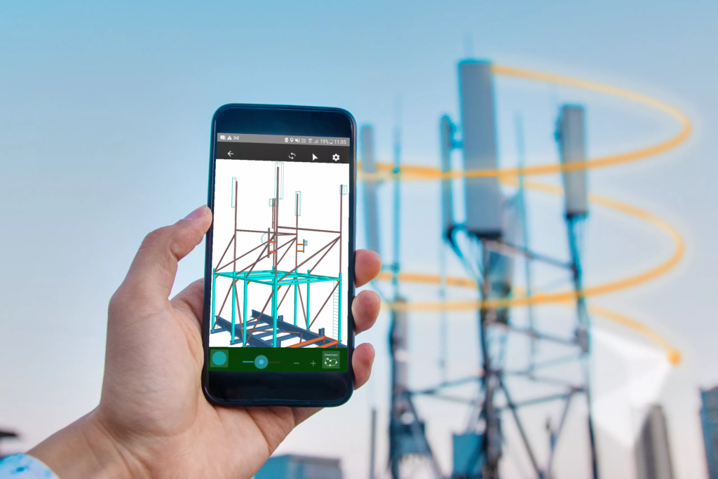
In the realm of telecom infrastructure development, precision and efficiency are paramount. Traditional methods of surveying telecom structures have undergone a revolutionary transformation with the advent of Lidar technology. Lidar, which stands for Light Detection and Ranging, utilises laser beams to measure distances and create detailed 3D models of objects and environments. While previously used primarily in specialised equipment, recent advancements have seen Lidar technology integrated into consumer devices, such as smartphones. Lidar, integrated into smartphones like recent iPhone models, enables capturing precise 3D models of objects.

Gone are the days of cumbersome on-site visits with dedicated cameras or expensive drones. With Lidar-equipped smartphones, surveyors can quickly capture intricate details of structures from a distance. The ability to generate detailed 3D models allows designers to gain a comprehensive understanding of the existing structure, eliminating the need to sift through countless photos, and hoping the surveyor did not miss a crucial angle or having to rely on guesswork.

Lidar technology in smartphones offers a cost-effective and accessible solution for surveying. Surveyors can efficiently capture and analyse data, reducing time and expenses. Portable and versatile, these devices adapt to various environments, from remote cell towers to urban infrastructure.

In conclusion, Lidar technology in smartphones streamlines surveying, enhances accuracy, and provides valuable insights into existing structures. As technology advances, further innovations will revolutionise telecom infrastructure development, making surveying tasks more efficient than ever.

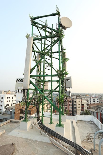
Bamboo to Replace Telecom Steel?

Assuming that we can keep the Pandas at bay, should we be looking at replacing steel with bamboo? Can bamboo telecommunication towers be sustainable and economical? Telecom towers are usually fabricated using steel because steel has very good strength. However, due to its tightly packed fibres, bamboo has superior tensile strength over steel. Producing steel also has a lot of drawbacks like high costs, atmospheric pollution, and environmental degradation. Bamboo, on the other hand, can be produced at very low costs and has various environmental benefits.

So far so good! Unfortunately, tensile strength alone is not sufficient. Bamboo is prone to insect attacks and will degrade until sustained exposure to water which is an issue for any towers not installed in the Sahara!

Perhaps the future of bamboo will depend on its use as a composite material or more resistant strains will be cultivated to remove some of the limitations. Either way, we are excited to see what the future holds.

At KA Engineering Group, we like to think of ourselves as a solution independent structural consultancy. We leverage our extensive engineering experience to accurately design the most suitable telecom structure for your needs. We take responsible steps to consider, advise, and optimise each site, ensuring cost-effective design, installation, and maintenance for build contractors and efficient utilisation for operators. Contact our expert team at: info@ka-engroup.com to learn more and discuss how we can best serve your needs.

Impact of Feeder Arrangement

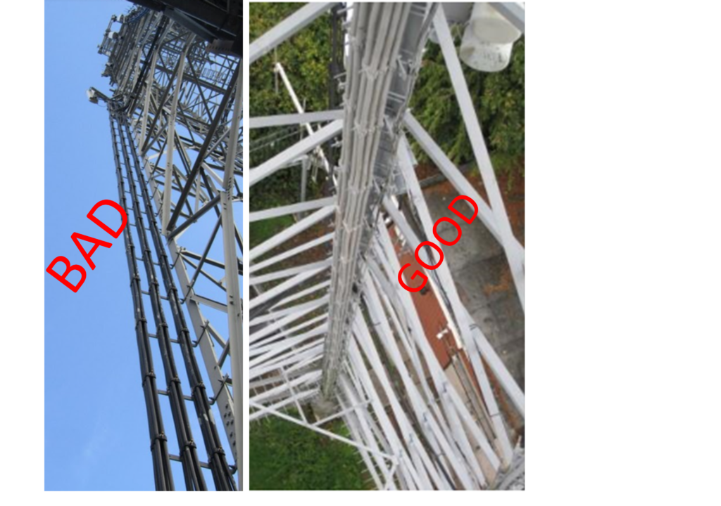
Feeder cables can FAIL a lattice tower, through exceeding the structural utilisation capacity, if not arranged thoughtfully. Carefully planned feeder arrangement in a simple system can reduce the utilisation of the lattice tower legs by 15% and reduce the tower brace utilisation by nearly 40%!

Without adequate forethought, a telecommunication system with 16 feeder cables on a tower may be arranged in stacks of 1 or 2. This leads to wind load across eight, or even 16 feeder surface areas.

We investigated the effect of feeder arrangements on tower utilisation. We placed four antennas at the top of an existing 30m square lattice tower, fed by 16 typical sized feeders in a variety of different arrangements. To replicate a common tower arrangement, the structure also included a ladder mounted on one of the tower faces.

What We Found

Our analyses showed the maximum tower utilisation with the feeders stacked in a single row of 16, mounted on one leg, adjacent to the ladder location. Minimum utilisation was from feeders stacked in rows of four, mounted on a leg that is not directly supporting the ladder.

The difference in structural utilisation between these two scenarios was 15% for the tower legs, and 38% for the tower braces!

A surprising find was the structural utilisation from the feeders separated into groups of four, stacked in rows of two, mounted on each leg. The leg and brace utilisation were greater than those in the minimum scenario by 5% and 6% respectively.

Take Away Message

Feeders must be arranged with tower loading in mind. With less loading from feeders, more ancillaries can be placed on the tower, resulting in a more useful AND more financially profitable structure.

Check your existing towers. Check your proposed towers. Think about how the feeders are, or are proposed to be, arranged:

  • Are the feeders helping to distribute the loads more evenly throughout the tower?
  • Are the feeders stacked in the most efficient manner to reduce wind load on the structure?

KAEG continues to leverage our expertise to maximise the structural potential of your asset. Contact our expert team at: info@ka-engroup.com to learn more and discuss how we can best serve your needs.

Detailed Structural Design and Analysis of Lattice (GDC)

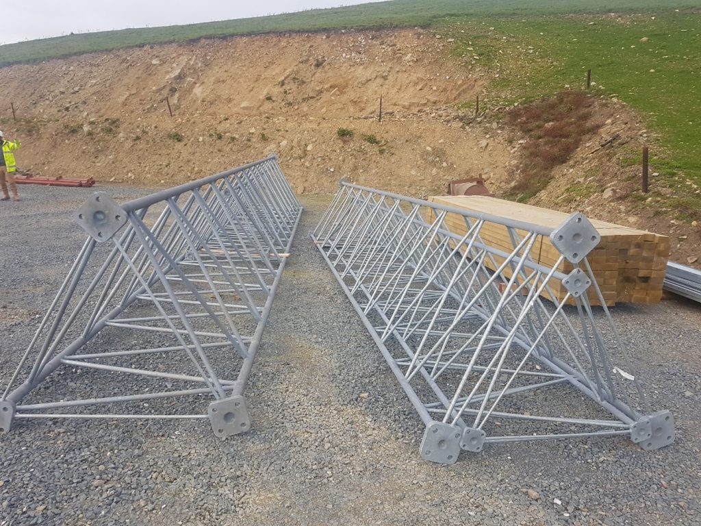
Great to see one of our detailed engineering design schemes successfully fabricated, delivered to site, and ready to be installed. We are finding that an increasing number of towers (lattice and monopoles), standard or bespoke are being sanctioned to meet growing demand from telecommunications and meteorological service.

These towers require expert structural engineering to ensure that the build is cost efficient and delivered to schedule. The engineering must be holistic, taking into consideration safety and quality which feeds into activities such as procurement, fabrication, delivery, and installation to avoid/minimise downtime in the process. The engineering is expected to be flexible in conformance to British Codes and Standard, European Design Standards, and other International Design Standards in-line with the region of operations and operators’ requirement.

KA Engineering Group not only completes structural due diligence for all telecommunication support structures, we take pride in extending operators’ assets life, optimising and improving capacity whilst ensuring confidence and enhancing in-service safety. We take responsible steps to consider, advise, and optimise each site, ensuring cost effective design, installation, and maintenance for build contractors and efficient utilisation for operators.

Contact our expert team at: info@ka-engroup.com to learn more and discuss how we can best serve your needs.